Table of Contents
Advertisement
Quick Links
OPERATING AND INSTALLATION INSTRUCTIONS
EN
ISTRUZIONI D'USO E INSTALLAZIONE
IT
NOTICE D'UTILISATION ET INSTALLATION
FR
AQUA UNIT
AUBV V2
AUCV V2
AUDV V2
Indoor unit - Inverter split air to water heat pump
Unità interna - Pompa di calore split Inverter aria / acqua
Unité intérieure - Pompe à chaleur split Inverter air / eau
37.4255.226.01
03/2023
Advertisement
Table of Contents

Related Manuals for Argo AQUA UNIT AUBV V2


Summary of Contents for Argo AQUA UNIT AUBV V2
- Page 1 OPERATING AND INSTALLATION INSTRUCTIONS ISTRUZIONI D’USO E INSTALLAZIONE NOTICE D’UTILISATION ET INSTALLATION AQUA UNIT AUBV V2 AUCV V2 AUDV V2 Indoor unit - Inverter split air to water heat pump Unità interna - Pompa di calore split Inverter aria / acqua Unité...
-
Page 2: Table Of Contents
CONTENTS 1 - Generalities ......... . .4 2 - Presentation . - Page 3 If necessary, get help These instructions are all you need for most installation sites and maintenance conditions. If you require help for a special problem, contact our sale/service outlet or your certified dealer for additional instructions. In case of improper installation The manufacturer shall in no way be responsible for improper installation or maintenance service, including failure to follow the instructions in this document.
-
Page 4: Generalities
1 - GENERALITIES OPERATING CONDITIONS Water system pressure Minimum: 1,5 bar Maximum: 2,0 bar Water temperature The maximum allowable water inlet temperature of the heat pump is 75 ° C Water volume of the system (to be compulsorily checked) Minimum: AUBV V2: 40 litres (*) AUCV V2: 80 litres (*) AUDV V2: 80 litres (*) Maximum: dimension the expansion vessel according to the maximum volume of water, the maximum... -
Page 5: Presentation
2 - PRESENTATION 2.1 - DESCRIPTION OF THE PARTS 1 - Heat exchanger. Materials: 3 - Air vent valve. - Copper piping. 7 - Water circulator. - Stainless steel water heat exchanger. 8 - Expansion vessel. - Painted sheet metal cabinet. 9 - Refrigerant pressure transducer. - Page 6 2.2 - DIMENSIONS AND WEIGHT AUBV V2 AUCV V2 AUDV V2 1 Water inlet connection 1” M 1” M 1” M 2 Water outlet connection 1” M 1” M 1” M 3 Condensate drain connection ø 16mm ø 16mm ø 16mm 4 Gas refrigerant connection 1/2”...
-
Page 7: Installation
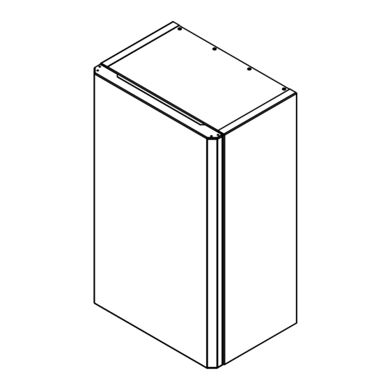
2.3 - ADDITIONAL MATERIAL REQUIRED FOR INSTALLATION (NOT SUPPLIED) • Deoxidized annealed copper tube for refrigerant tubing connecting Emix; it has to be insulated with foamed polyethylene (min. thickness 8mm). • Anti-freeze oil for flare connections (about 30g.) • Electric wire: use insulated copper wires of size and length as shown at paragraph “SYSTEM WIRING DIAGRAMS”. •... - Page 8 3.2 - HOW TO INSTALL THE UNIT IINSTALLATION TO THE WALL FRONT VIEW • Remove the front panel from the unit, pulling towards you (fig. 1). • Make 3/4 holes in the wall (fig. 2). Use pins and screws (not supplied) that are appropriate to the weight of the unit and the type of wall.
-
Page 9: Connections
4 - CONNECTIONS 4.1 - REFRIGERANT CONNECTION indoor unit Outdoor unit Liquid line Gas line AUBV V2 AUCV V2 AUDV V2 * IMPORTANT! Connection to the refrigerant Circuit A Circuit A Circuit A ** Connect EXCLUSIVELY circuit of outdoor unit * to the circuit «A»... - Page 10 4.2 - HYDRAULIC CONNECTION 4.2.1 - WATER INLET AND OUTLET CONNECTION • Connect the water pipes to the corresponding connections (for diameters and position, see page 6). • It is mandatory to install a hydraulic fi lter (1) (not supplied) on the water intake. Connect it using two on-off valves (2) (not supplied) for cleaning purposes.
- Page 11 4.3 - ELECTRICAL CONNECTION • Remove the front panel (fi g.1). • Unscrew the four screws (fi g. 2). • Remove the cover to access the terminal blocks (fi g. 3). • Let the electrical wires pass fi rst in the wire glands placed on the bottom of the unit and then in the wire grommets placed on the bottom of the electrical panel (fi...
-
Page 12: System Wiring Diagrams
5 - SYSTEM WIRING DIAGRAMS LENGTH, SIZE WIRES AND DELAYED FUSE Wires’ size (mm Without DHW electrical heater 0,75 0,75 With DHW electrical heater 20 A Supply power wire A: Multipolar electric wire; the size of the suggested electric wire is shown on table. The wire must be Mod. H07RN-F (according to CEI 20-19 CENELEC HD 22). - Page 13 5.2 - FULL CONFIGURATION AQUA UNIT OUTDOOR UNIT 5.3 - CONNECTIONS DETAILS • DHW VALVE (5): DHW valve closing command. Phase output 230 Vac / 20 W max. (6): Neutral (7): DHW valve opening command. Phase output 230 Vac / 20 W max. •...
- Page 14 • DHW ELECTRICAL HEATER • (LR) : DHW Electrical heater activation. Phase output 230Vac /4kW MAX. (NR): Neutral. To enable DHW management, check that switch SW1 has been set correctly (see 6.2) WARNING Connect a maximum power heater of 4kW equipped with both an automatic reset protection device and a manual reset one.
- Page 15 5.4 - CONNECTION EXAMPLES WORKING MODE SELECTION WITH ON/OFF THERMOSTAT WORKING MODE SELECTION WITH ON/OFF THERMOSTAT AND HEAT/COOLING (H/C) NOTE: see paragraph “STARTING” section “JUMPERS/SWITCH SETTING” - ENABLING COOLING MODE...
- Page 16 WORKING MODE SELECTION WITH ON/OFF THERMOSTAT, SAFETY THERMOSTAT AND DHW WORKING MODE SELECTION WITHOUT THERMOSTAT...
- Page 17 WORKING MODE SELECTION WITHOUT THERMOSTAT + SAFETY SWITCH WORKING MODE SELECTION WITH 24 Vac THERMOSTAT...
- Page 18 6 - STARTING IMPORTANT NOTE Before carrying out any work on the installation, make sure that it is switched off and that access to it is prevented. Any work must be carried out by personnel qualifi ed and authorised to work on this type of unit. 6.1 - PRELIMINARY CHECKS 6.1.1 - HYDRAULIC CIRCUIT •...
- Page 19 6.2 - JUMPERS/SWITCH SETTING AND LEDs’ MEANING Jumper and switch settings must be made with the unit disconnected SWITCH SWITCH JUMPERS LEDs JUMPERS JP1 - ENABLING COOLING MODE CLOSED: the unit will run in heating mode only (FACTORY SETTING). OPEN: the unit can run in heating and cooling mode. JP2 - DEFROST TYPE SELECTION Internal use.
- Page 20 6.3 - ADDITIONAL HYDRAULIC CIRCUIT VERIFICATIONS 6.3.1 - CHECKS With the pump running, perform the following checks: • Hydraulic circuit air bleed: operate the pump at 100% in manual mode) for as long as it takes to completely purge the circuit air. •...
-
Page 21: Starting
6.3.3 - CHECKING THE PRESSURE LOSSES With the pump running at the set speed, compare the reread fl ow with the following curves to determine the system pressure losses and compare them with the calculations made during the installation of the system. p/kPa Q/m³/ h Q/l/s... -
Page 22: Wired Controller Installation
7 - WIRED CONTROLLER INSTALLATION 7.1 - MECHANICAL INSTRUCTIONS • Remove the rear panel of the wired controller. • Fix the panel to the wall in the desired position. • Make the electrical connections to the wired controller (see section 2.2). •... - Page 23 7.2 - ELECTRICAL CONNECTION WARNING Before installation, please cut off the power supply of the unit to which the wired controller is connected. AUV2 +12V Multipolar wire A: Electric cable 12V dc; section: 4 x 0,75mm ATTENTION! When inserting or removing connectors, press gently on the clamp to facilitate the operation. 7.3 - ADVANCED PARAMETERS MENU Press the MENU / PARAMETERS button for 2 seconds to enter the advanced parameters menu, then enter the password (-3).
- Page 24 GENERAL PARAMETERS...
- Page 26 TECHNICAL WATER PARAMETERS...
- Page 27 DHW PARAMETERS...
-
Page 28: Wired Controller Presentation And Operation Instructions
8 - WIRED CONTROLLER PRESENTATION AND OPERATION INSTRUCTIONS DISPLAY MENU’ / PARAMETERS ON/OFF FUNCTION OPERATION MODE RIGHT LEFT BACK OK / SETTINGS UP / DOWN 8.1 - BUTTONS ON / OFF Button: Push this button to turn ON / OFF the unit section. OPERATION MODE Button: Push this button to change the working mode (only for “TECHNICAL WATER”). - Page 29 8.2 - HOME DISPLAY Main functions of the wired controller can be set directly on the home display. TECHNICAL WATER SECTION ACTIVE DATE BACKUP HEATING SECTIONS WORKING MODE PUMP COOLING COMP. HEATING FUNCTIONS WATER TEMPERATURE TURBO SELECTED FUNCTION (NOT ACTIVE) SELECTED AND ACTIVE FUNCTION SELECTED SECTION: The box around the symbol indicates the selected section.
- Page 30 8.3 - MAIN PARAMETERS MENU Use the < / > buttons to move between the symbols. Use the OK button to enter the selected menu. PUMP SPEED SETTINGS SENSORS DHW TIMER PUMP SPEED: Use OK button to enter the pump menu. Press OK button on “SPEED”...
- Page 31 8.4 - SETTINGS MENU Use the < / > buttons to move between the symbols. DISPLAY BUTTONS CLOCK LANGUAGE °C BACK LEFT RIGHT TEMPERATURE TIMER UP / DOWN OK / SET CLOCK: Select CLOCK symbol and press OK to enter the setting menu. The following options will appear: LEVEL 1 LEVEL 2 CLOCK FORMAT...
- Page 32 DHW TIMER: Select TIMER symbol and press OK to enter the setting menu. Exemple SCHEDULE 1 SCHEDULE 80°c 75°c 70°c 65°c 60°c 55°c 50°c 45°c 40°c APPLY TO DAY Press OK to confirm SCHEDULE 1. Press OK to confirm the day. Use ...
- Page 33 CLIMATIC CURVE (HEATING MODE) Return water setpoint P105 P130 (setpoint) P106 Outdoor air temperature P120 P121 ANTIFREEZE FUNCTION If the antifreeze function is active: Unit in forced Atifreeze function function for activated water heating Unit in normal Atifreeze function operation not activated Return water Outdoor air...
-
Page 34: Maintenance Instructions
9 - MAINTENANCE INSTRUCTIONS IMPORTANT NOTE • Before doing any work on the installation, make sure it is switched off and all power supplies locked out. Before disconnect the outdoor unit and then Aqua Unit or contemporally. • Also check that the capacitors are discharged. •... -
Page 35: Electrical Diagram
10 - ELECTRICAL DIAGRAM Symbols of the components Colour of the wires Black Brown Return water temperature sensor Blue Supply water temperature sensor Green ICT1 Outlet sensor (HEAT) / inlet sensor (COOL) Grey plate exchanger Orange ICT2 Inlet sensor (HEAT) / outlet sensor (FREDDO) Pink plate exchanger Condensation pressure sensor (HEAT) /... -
Page 36: Auto-Diagnosis Table
11 - AUTO-DIAGNOSIS TABLE CAUTION Disconnect power and wait that all LEDs are OFF before servicing on the electrical box. X LED OFF O LED ON LED BLINKING DISPLAY LEDs ON BOARD DESCRIPTION COMM2 ERROR Communication error with display DHW SENS. DEFECT Tank sensor damaged or not connected EXT UNIT ERR Error on outdoor unit... - Page 38 Via Alfeno Varo, 35 - 25020 Alfianello - BS - Italy Tel. +39 0331 755111 - Fax +39 0331 755501 www.argoclima.com...
Need help?
Do you have a question about the AQUA UNIT AUBV V2 and is the answer not in the manual?
Questions and answers