Table of Contents
Advertisement
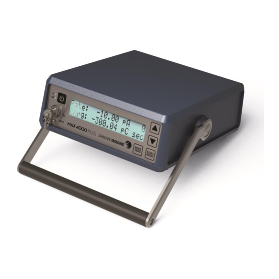
MAX 4000 PLUS ELECTROMETER
REF 90020
U S E R
M A N U A L
See MAX COMM™ Software package for installation CD-ROM
Standard Imaging, Inc. // 3120 Deming Way // Middleton, WI 53562 USA
TEL 608.831.0025 // TEL 800.261.4446 // FAX 608.831.2202
www.standardimaging.com
©2022 Standard Imaging, Inc. // July 2022 // DOC #80731-02
Advertisement
Table of Contents

Related Manuals for Standard Imaging MAX 4000 PLUS


Summary of Contents for Standard Imaging MAX 4000 PLUS
- Page 1 U S E R M A N U A L See MAX COMM™ Software package for installation CD-ROM Standard Imaging, Inc. // 3120 Deming Way // Middleton, WI 53562 USA TEL 608.831.0025 // TEL 800.261.4446 // FAX 608.831.2202 www.standardimaging.com ©2022 Standard Imaging, Inc. // July 2022 // DOC #80731-02...
-
Page 2: General Precautions
MAX 4000 Plus. WARNING: Electric shock hazard. Refer servicing to a qualified individual. WARNING: The MAX 4000 Plus is not intended to be used in flammable mixture atmospheres. Do not use with flammable anesthetic mixture with air, with oxygen, or nitrous oxide. - Page 3 Imaging. Contact Standard Imaging for additional information. CAUTION: To ensure long-term performance of the internal battery, it is recommended to fully recharge the MAX 4000 Plus Electrometer monthly. CAUTION: Cybersecurity is a shared responsibility between Standard Imaging and the customer. Secure use of this product is dependent upon the proper utilization of passwords, firewalls, networks, computer platforms, operating systems and data storage.
-
Page 4: Table Of Contents
Table of Contents ....................................... 4 General Operation ..................................5 Front Panel ......................................6 Rear Panel ......................................7 Setting up the MAX 4000 Plus ............................. 7 Warm Up and Zero Adjustment ..........................7 Range Selection Mode ..............................8 Bias Mode ....................................8 Trigger Mode Threshold Levels .......................... -
Page 5: General Operation
50/60 Hz power outlet, and connect the power supply to the MAX 4000 Plus Electrometer power adapter input. 2. With nothing connected to the input connector of the MAX 4000 Plus, turn the power on and wait at least 10 minutes for the electrometer to warm up. -
Page 6: Front Panel
0-450 VDC / 350 µA max To protect the input connector, always replace the chain cap when the MAX 4000 Plus is not in use. 5 MODE/ZERO button: Press to toggle through the modes in the following order: Range, Bias, Threshold Levels, Rate, Charge and Rate/Charge. -
Page 7: Rear Panel
4.1 Warm Up and Zero Adjustment 1. Turn on the MAX 4000 Plus. Allow the unit to warm up for a minimum of 10 minutes. This allows the temperature of the internal components to stabilize, and will help prevent the measurements from drifting. -
Page 8: Range Selection Mode
MODE/ZERO button for two seconds. 4.2 Range Selection Mode 1. The measuring range of the MAX 4000 Plus is displayed as High or Low. The actual numeric range is also shown to indicate the proper units of measurement for each range. -
Page 9: System Zeroing
Battery percent display in the Bias Mode will indicate “CHRG”. The MAX 4000 Plus will also operate with the charger plugged into a wall outlet, regardless of the battery capacity. Re-charging the battery takes 6 - 8 hours. The MAX 4000 Plus may be continually charged with no detrimental effects to the internal battery. -
Page 10: Automatic Shutdown
5.2 Automatic shutdown To maximize battery life, the MAX 4000 Plus will shut off automatically if it is not plugged into the wall charger and is left unattended for more than 3 hours. Rate Mode Use the Range mode to select the range of operation. - Page 11 When 8. Press START/RESET to stop the countdown is complete, collection and reset reading. 8. The MAX 4000 Plus will the charge accumulated will continue to collect charge remain until the unit is reset. 9. Repeat steps 4-8 for other until the measured current is charge readings.
-
Page 12: Max Comm™ Software
Do not use water or liquid on triax jack. Do not permit any liquid to seep into the MAX 4000 Plus in any manner during cleaning, as there is no protection from the harmful ingress of water. It is not recommended to clean the window of the LCD with anything other than a mild detergent and a very soft cloth. -
Page 13: Description Of Symbols
8 Description of Symbols The following symbols are found on the MAX 4000 Plus: 9 Parts and Accessories List Description 90020 MAX 4000 Plus Electrometer 80731 MAX 4000 Plus User Manual 20194 25 ft. Serial Cable 20193 100 ft. Serial Cable... -
Page 14: Troubleshooting
10 Troubleshooting 10.1 Questionable Readings If readings are off, determine if there is any leakage from the MAX 4000 Plus or ionization chamber. Follow steps 1 - 8 under General Operation. If going through the General Operation instructions does not resolve leakage issues, a dirty connector could be the cause. -
Page 15: Can't Get Out Of Charge Mode Or Rate/Charge Mode
The MAX 4000 Plus will also operate with the charger plugged into a wall outlet. Re-charging the battery takes 6 - 8 hours. The MAX 4000 Plus may be continually charged when not in use with no detrimental effects to the internal battery. -
Page 16: Features And Specifications
Countup/Countdown 1 second (count up for Continuous Mode, count down for Resolution: Timed Mode) Trigger Levels for Charge Collection: Start value must be larger than stop value Start: 0.02 - 9.99 pA MAX 4000 PLUS ELECTROMETER... - Page 17 Zero via button push - Display indicates zeroing in progress Output: RS-232, Default: Uni-directional 19,200 baud, 8 data bits, no parity, 1 stop bit Bi-directional operation via: 1: Standard Imaging MAX COMM Software (included) 2: Argus QC4 Software 3: User provided-request Tech Note Doc No. 4426 Dimensions: Width: 22.6 cm (8.91 in)
-
Page 18: Warranty Statement- 4424-18
12 WARRANTY STATEMENT- 4424-18 Standard Imaging, Inc. sells this product under the warranty herein set forth. The warranty is extended only to the buyer purchasing the product directly from Standard Imaging, Inc. or as a new product from an authorized dealer or distributor of Standard Imaging, Inc. - Page 19 This warranty represents the current standard warranty of Standard Imaging, Inc. Please refer to the labeling or instruction manual of your Standard Imaging, Inc. product or the Standard Imaging, Inc. web page for any warranty conditions unique to the product.
-
Page 20: Serialization Information
Standard Imaging, at its discretion, may extend customer support only to the buyer purchasing the product directly from Standard Imaging, Inc. or as a new product from an authorized dealer or distributor of Standard Imaging, Inc. This customer care statement is in lieu of all other customer support statements, express or implied, whether statutory or otherwise, including any implied statements of fitness for a particular purpose. -
Page 21: Customer Responsibility
It is the responsibility of the customer or user to determine if the Standard Imaging product can be properly used with these products or systems. - Page 22 The information in this manual is subject to change without notice. Please see www.standardimaging.com for the latest information. No part of this manual may be copied or reproduced in any form or by any means without prior written consent of Standard Imaging Inc. MAX 4000 PLUS ELECTROMETER...
-
Page 23: Service Policy
If unable to address the issue, a return material authorization (RMA) number will be issued. With the RMA number, the product can be returned to Standard Imaging. It is the responsibility of the customer to properly package, insure and ship the product, with the RMA number clearly identified on the outside of the package. - Page 24 Authorized representative for the EU is Hoff & Lowendahl AB Högåsvägen 125, SE-741 41, Knivsta, Sweden (SRN: SE-AR-000001888). Contact information: info@lowendahl.eu. 3120 DEMING WAY MIDDLETON, WI 53562 USA WWW.STANDARDIMAGING.COM MAX 4000 PLUS ELECTROMETER...
Need help?
Do you have a question about the MAX 4000 PLUS and is the answer not in the manual?
Questions and answers
Can we plug in the wall charger all the time when we do not use the 4000 plus electrometer? Will it damage the battery or not in this way?