Table of Contents
Advertisement
Advertisement
Table of Contents
Troubleshooting

Related Manuals for Standard Imaging QA BEAMCHECKER PLUS


Summary of Contents for Standard Imaging QA BEAMCHECKER PLUS
- Page 1 REF 90501 U S E R M A N U A L Standard Imaging, Inc. // 3120 Deming Way // Middleton, WI 53562 USA TEL 608.831.0025 // TEL 800.261.4446 // FAX 608.831.2202 www.standardimaging.com ©2020 Standard Imaging, Inc. // Jan 2020 // DOC #80117-11...
-
Page 2: General Precautions
CAUTION: When using the Bluetooth® Adapter Kit, be careful lifting the unit when it is lying flat to avoid damage to both the adapter and QA BeamChecker Plus. If necessary, remove the adapter before moving the unit. CAUTION: The Bluetooth Adapter Kit will not communicate through the treatment vault wall, but because their signal is transmitted via RF, the cradle (with attached adapter) can be placed inside a cabinet or closet and still communicate effectively. - Page 3 Imaging. Contact Standard Imaging for additional information. CAUTION: To ensure long-term performance of the internal battery, it is recommended to recharge the QA BeamChecker Plus by always placing it on the Power/Data Cradle when not in use. TomoTherapy® is a registered trademark of Accuray Incorporated. Bluetooth® is a registered trademark of Bluetooth SIG, Inc.
-
Page 4: Table Of Contents
Baseline Acquisition................................11 Performing Routine Measurements ........................12 Data Download & Analysis ............................13 Hardware Description ................................15 QA BeamChecker Plus Front Panel ........................15 Power/Data Cradle ................................16 Setting up the Communication Software ......................... 16 System Requirements ..............................17 Database and Room Setup and Management ..................... 18 Getting Started - Creating a Database ...................... - Page 5 Printing and Exporting ..............................47 Physics Mode ....................................48 Setup ......................................48 Working with Physics Mode ............................. 49 About Synchronization and Database Relationship ...................51 10.1 Introduction ....................................51 10.2 Usage and Troubleshooting ............................51 Using Other Accessories................................53 11.1 Bluetooth Adapter Kit ..............................53 11.2 Gantry Mount Accessory ..............................55 11.3...
- Page 6 20 Features and Specifications..............................82 WARRANTY STATEMENT- 4424-16 ..........................84 Serialization Information ................................ 86 Customer Care Policy Statement ............................ 86 24 Customer Responsibility ................................ 87 Service Policy ....................................88 26 Return Policy ....................................88 QA BEAMCHECKER™ PLUS...
-
Page 7: Overview
“1000”) in the device internal EEPROM memory for retention between release for sale and return for repair. If a QA BeamChecker Plus is returned to SI for an indicated repair (see pgs. 45-47), the device is ‘re-leveled’ after repair and the new chamber ‘leveling’... - Page 8 TomoTherapy system) or any other unique identifier. In typical use for rotational delivery such as RapidArc™, first a CT image of the QA BeamChecker Plus must be acquired in order to contour its internal ion chambers. Using the image and its contours, a treatment plan is developed and delivered to the unit as a baseline measurement.
-
Page 9: Quick Start Guide
2 Quick Start Guide This section will give a basic overview for setting up and using the QA BeamChecker Plus. The steps listed here are covered in greater detail in following sections, and specific page numbers to these sections are included for additional reference. -
Page 10: Software Setup & Database Creation
Complete the remaining steps, and the main Communication software interface will now be accessible. 5. The next step is to create a room to be used with the QA BeamChecker Plus. After completing the Database Creator process, a prompt will appear to allow creation of a room. -
Page 11: Baseline Acquisition
Power/Data Cradle on page 8). Using the pass-through port on the Power/Data Cradle, the 25 ft serial cable is used to connect the cradle to the QA BeamChecker Plus which is placed on the treatment couch. Ensure the QA BeamChecker Plus is flipped to the proper side based on initial energy to be delivered. -
Page 12: Performing Routine Measurements
Measurement. The main baseline screen is displayed, and results can be reviewed. 5. Repeat steps 2-4 for each desired energy or plan. The QA BeamChecker Plus will need to be flipped over if switching between photons and electrons. Baselines can be recreated at any time if necessary. -
Page 13: Data Download & Analysis
Orientation may differ depending on room type or energy selected Delivery 5. Expose the QA BeamChecker Plus with the desired energy. During the exposure, the QA BeamChecker Plus front display will show as spinning lines indicating a signal has been detected and measurement is in progress. - Page 14 Clicking this button will move all data from the QA BeamChecker Plus internal memory and will be visible in the Download Summary dialog. Click the Download Summary dialog 'Done' button to permit the data to be persisted in the database.
-
Page 15: Hardware Description
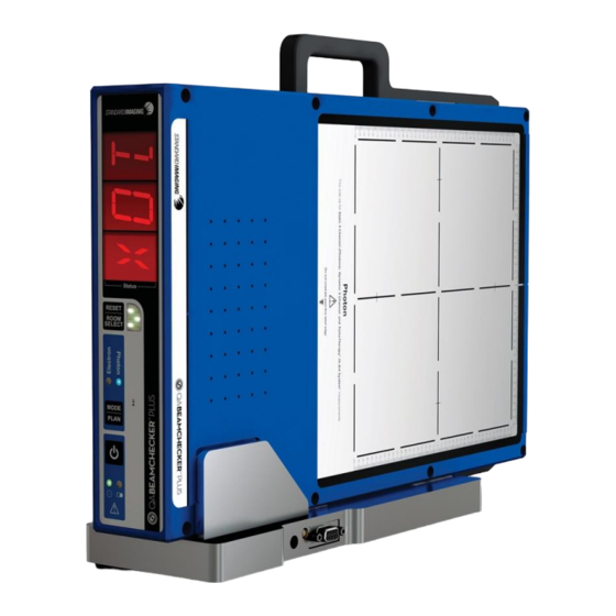
3 Hardware Description 3.1 QA BeamChecker Plus Front Panel QA BEAMCHECKER™ PLUS... -
Page 16: Power/Data Cradle
See system requirements for more specific information. Before installing the software, it is recommended to close all other active programs. NOTE: The account under which the QA BeamChecker Plus software is INSTALLED must have at least “Power User” access privileges within Windows. However, as of version 2.2.X, the software can be RUN as a basic “User”. -
Page 17: System Requirements
When a new version of the QA BeamChecker Plus Communication Software is installed, a firmware update may also be included. If a QA BeamChecker Plus unit is connected to the PC (either directly or via the Power/Data Cradle) and the software is opened, new firmware will automatically be uploaded to the unit. -
Page 18: Database And Room Setup And Management
NOTE: An individual database file must be created for each QA BeamChecker Plus unit used. Upon starting the software, connect the QA BeamChecker Plus to the PC and turn it on if necessary. A prompt will appear providing the opportunity to create a new database or browse for an existing database. - Page 19 3. On the left side of the screen select the text “QABC Plus Zxxxxxx”, where Zxxxxxx indicates the serial number of QA BeamChecker Plus associated with the database file. 4. Click the Add Room icon on the toolbar or navigate to File > Room > Add Room.
- Page 20 NOTE: The QA BeamChecker Plus must be attached to the system in order to delete treatment rooms. 2. If it is not already open, load the database file which matches the QA BeamChecker Plus attached to the system by clicking the open icon from the toolbar or navigating to File >...
-
Page 21: Preparatory Measurements - Baselines
Power/Data Cradle (read more about the Power/Data Cradle on page 8). Using the pass-through port on the Power/Data Cradle, the 25 ft serial cable is used to connect the cradle to the QA BeamChecker Plus which is placed on the treatment couch. -
Page 22: Step 1: Hardware Setup
NOTE: A Bluetooth Adapter Kit (REF 70504) is an available option allowing wireless communication from the PC to the QA BeamChecker Plus in place of a wired serial connection. See page 53 for more details. -
Page 23: Step 2: Prepare The Communication Software
Photon or Electron, as indicated by the large white field labels on both sides of the device. 3. Position the QA BeamChecker Plus at 100 cm SSD with a field size of 20 x 20 cm. Align the unit to the center of the field using the QA BeamChecker Plus fiducials and the room alignment lasers. - Page 24 NOTE: The QA BeamChecker Plus should automatically turn on when the communication software is launched. 2. If the database file associated with the QA BeamChecker Plus connected to the PC is not already open, open it by clicking the open icon on the toolbar or navigating to File >...
- Page 25 • Field Size (x,y) in cm: Default is 20,20 • Measured by: Name or initials of the baseline creator • Action Levels: represent the point at which a flatness, axial symmetry, transverse symmetry, or constancy ‘out of tolerance’ will occur during measurement in Real-Time Operation or Wire- Free Modes.
- Page 26 By clicking Modify, baseline parameters can be changed on the previous screen. NOTE: Verify the QA BeamChecker Plus is flipped to the proper side. The side facing up should be labeled as Photon or Electron as desired. At this point the software is in control of the mode settings of the device so if the QA BeamChecker Plus display text orientation is incorrect, verify the proper room and delivery type in the baseline parameters.
-
Page 27: Recreating Baselines
To recreate a baseline for a particular energy or plan, the procedure is nearly identical to creating a baseline. 1. Setup the QA BeamChecker Plus hardware as described in the section titled Step 1: Hardware Setup on page 12. 2. Continue with Step 2: Prepare the Communication Software steps 1-4. -
Page 28: Deleting Baselines
If a plan or energy was created by mistake or is no longer needed, it can be deleted from the database using the following procedure. 1. Connect the QA BeamChecker Plus to the PC. 2. Launch the Communication Software and ensure the correct database is loaded. -
Page 29: Routine Qa Measurements
- all without being tethered to a computer. Set the QA BeamChecker Plus on the treatment couch, expose it to the beam with any baselined energy, and the front panel display... - Page 30 Figure 5: Typical QA BeamChecker Plus Real-Time Operation setup The Real-Time Operation Mode provides routine QA measurements by displaying results through the Communication Software interface. With the QA BeamChecker Plus connected to the PC via RS-232 serial interface, the measured beam parameters, percentage difference from the baseline, and raw chamber values can be viewed in real-time.
-
Page 31: Measurement With Wire-Free Mode
Photon or Electron, as indicated by the large white field labels on both sides of the device. 3. Position the QA BeamChecker Plus at 100 cm SSD with a field size of 20 x 20 cm. Align the unit to the center of the field using the QA BeamChecker Plus fiducials and the room alignment lasers. - Page 32 Photon side as indicated by the large white field labels on both sides of the device. 2. Position the QA BeamChecker Plus at 100 cm SSD with a field size of 20 x 20 cm. Align the unit to the center of the field using the QA BeamChecker Plus fiducials and the room alignment lasers.
- Page 33 3. Adjust the vertical height using the treatment couch until the horizontal side lasers line up to the fiducial alignment mark on the top end of the QA BeamChecker Plus facing the bore of the TomoTherapy unit. After the couch height is correct, align the lasers to the crosshair on the top surface of the unit.
- Page 34 CAUTION: Do not irradiate past the 20 x 20 cm field label edge. 6. Turn the QA BeamChecker Plus on using the power button on the front of the unit. 7. (If only 1 room is configured, skip to step 5) After displaying the firmware version, the front panel will alternate between RM and SEL (Room Select).
-
Page 35: High-Dose Rate Measurements
FFF beams independently. 7.4 Wire-Free Measurement Fault If a measured energy falls out of range of the preset baseline, the QA BeamChecker Plus status indicator will show red and will respond differently based on action level:... -
Page 36: Measurement With Real-Time Operation Mode
Photon or Electron, as indicated by the large white field labels on both sides of the device. 3. Position the QA BeamChecker Plus at 100 cm SSD with a field size of 20 x 20 cm. Align the unit to the center of the field using the QA BeamChecker Plus fiducials and the room alignment lasers. - Page 37 Connection Status should now be shown as “Ready for Beam” (green). 11. Deliver any energy to the QA BeamChecker Plus for which a baseline exists. Upon detecting signal, the QA BeamChecker Plus will begin measurement, and the Connection Status bar will alternate between green and yellow.
- Page 38 2. Position the QA BeamChecker Plus at 100 cm SSD with a field size of 20 x 20 cm. Align the unit to the center of the field using the QA BeamChecker Plus fiducials and the room alignment lasers.
- Page 39 5. If the database file associated with the QA BeamChecker Plus connected to the PC is not already open, open it by clicking the open icon on the toolbar or navigating to File > Database > Open and browse for the correct file.
- Page 40 3. Adjust the vertical height using the treatment couch until the horizontal side lasers line up to the fiducial alignment mark on the top end of the QA BeamChecker Plus facing the bore of the TomoTherapy unit. After the couch height is correct, align the lasers to the crosshair on the top surface of the unit.
- Page 41 5. Now complete an MVCT of the QA BeamChecker Plus by following the directions for running a procedure on the “What’s Next?” box at the top of the screen in the TomoTherapy software. After completing the scan, go to the registration panel on the Operator’s Station and register the MV image to the reference image (taken during the planning step - See Appendix B) using the manual adjustments.
-
Page 42: Data View, Downloading Measurements And Reporting
12. Deliver the selected plan to the QA BeamChecker Plus. Upon detecting signal, the QA BeamChecker Plus will begin measurement, and the Connection Status bar will alternate between green and yellow. Once the exposure is completed, raw measured values, temperature, pressure, and baseline parameters are shown. -
Page 43: Downloading Measurements From Wire-Free Mode
To download data from the QA BeamChecker Plus unit after a Wire-Free data acquisition, follow these steps: 1. Place the QA BeamChecker Plus on the Power/Data Cradle while connected to the PC or connect the QA BeamChecker Plus to the PC directly. -
Page 44: Selectively Viewing Data
NOTE: When downloading data, all data from all rooms is transferred to the Communication Software database. NOTE: It is not necessary to download acquired data from the QA BeamChecker Plus after every Wire-Free session. The QA BeamChecker Plus internal memory will hold up to 512 measurements before the data will need to be transferred to the software database. - Page 45 Select the Begin Date, End Date, and click the Update Chart button. The Chart View will update to reflect the specified range. Click and drag horizontally within the Chart View, to zoom to a selection range. To return to the top-level zoom, click the 1:1 zoom button. If multiple sequential drag selections are made, they can be reverted one at a time by clicking the up arrow zoom button.
- Page 46 Using the Table View To view the data in tabular format, click the Table View button. Each row represents a unique measurement point and includes the date and time of measurement along with percentage differences from the baseline. The colors shown on the table indicate how close the acquired values are to the baseline. Just like the status indicators found in the Real-Time Operation mode, the colors of the cells are defined as follows: Green Below action level 1...
-
Page 47: Printing And Exporting
Clicking the [...] box in the Comment column will allow entry of a comment for the selected row. Measurements with comments are indicated by a red checkmark on the corresponding [...] button. 8.3 Printing and Exporting Printing Reports 1. In Chart or Table View, click the Print button. 2. -
Page 48: Physics Mode
9 Physics Mode The Physics Mode allows use of the QA BeamChecker Plus as a 5 channel chamber and electrometer array for taking real-time measurements. Because data collected is not associated with baselines or saved to the database file, this mode is ideal for experimental or customized measurements. -
Page 49: Working With Physics Mode
NOTE: If using a TomoTherapy System or Dynamic 5 Channel room, the QA BeamChecker Plus must be flipped to the Photon side to ensure correct labeling of the left and right chambers. 7. Select the Physics tab at the bottom of the screen to view the Physics mode interface. - Page 50 NOTE: The numbers seen in the Physics Mode are not amps or coulombs, nor are they calibrated. They are A to D converter counts from an amplifier displayed as digital read-out units. 4. Upon clicking the Stop button, measurement information will be displayed along with temperature, pressure, battery voltage, and the date and time when the measurement completed.
-
Page 51: About Synchronization And Database Relationship
10 About Synchronization and Database Relationship 10.1 Introduction When a link is established between a QA BeamChecker Plus and a database file, they are considered to be “synchronized”. The relationship between the two is defined as the database being the master and the QA BeamChecker Plus being the slave. - Page 52 The left column shows the room, energy, and plan information that exists within the database, and the right column shows which information is stored within the QA BeamChecker Plus internal memory. By clicking either Yes or Synchronize, the values will be pushed from left to right and the main QA BeamChecker Plus software interface will be displayed.
-
Page 53: Using Other Accessories
Take Advantage of the Synchronize Function A synchronization operation can be useful if using the QA BeamChecker Plus with more than one database. If using one QA BeamChecker Plus in any situation where more than the allowed 9 treatment rooms are required, multiple databases can be created, each with their own 9 treatment rooms. - Page 54 4. Connect the female interface adapter to the QA BeamChecker Plus where a serial cable is normally connected. No external power is required for most QA BeamChecker Plus units. NOTE: The initial manufactured quantities of the QA BeamChecker Plus (serial number Z071551 and below from early 2007) do not provide power to the Bluetooth adapter through the serial port.
-
Page 55: Gantry Mount Accessory
90° to facilitate easier insertion. 2. Slide the QA BeamChecker Plus into the Gantry Mount Accessory with the photon side up. The black rails on either side of the QA BeamChecker Plus will guide the instrument into place. -
Page 56: Precision Tomotherapy Leveling Platform
3. If required, connect the serial cable to the QA BeamChecker Plus to facilitate any Communication Software-based operations. Wire-Free mode measurements are recommended for gantry use to help avoid any incidents that could occur due to cable motion during gantry rotation. - Page 57 3. Adjust the vertical height using the treatment couch until the horizontal side lasers line up to the fiducial alignment mark on the top end of the QA BeamChecker Plus facing the bore of the TomoTherapy unit. After the couch height is correct, align the lasers to the crosshair on the top surface of the unit.
-
Page 58: Serial To Usb Adapter
A USB to Serial Cable Adapter (REF 70503) is provided by Standard Imaging for situations where the computer used with the QA BeamChecker Plus does not have a 9-pin Serial Port. In order to use this adapter, the appropriate driver must first be setup. A CD ROM containing the necessary driver software and instructions for setup is included with the adapter. -
Page 59: Applicable To Static 5 Channel Mode Only
the raw or uncorrected reading of appropriate chamber temperature in °C measured by on-board sensor pressure in Torr measured by on-board sensor Output Constancy Output Constancy is determined by using the following algorithm on the temperature and pressure corrected values from the following chambers over time (values are shown in percent): Static 5 Channel: Center TomoTherapy: Left, Center, Right... -
Page 60: Appendix B: Developing Tomotherapy And Dynamic 5 Channel Plans
After the image is acquired, a treatment plan can be developed which targets the chambers within the QA BeamChecker Plus with a specific dose. Finally, this plan can be delivered to the QA BeamChecker Plus as a baseline and for routine measurement as explained in earlier sections of this user manual. -
Page 61: Tomotherapy System Planning
For TomoTherapy, it is advantageous to CT the QA BeamChecker Plus so that the center of the image is aligned with the BBs and allow the device to eventually be setup by initially setting the green lasers to these BBs. In this way, setup can be kept constant for both static and dynamic procedures. -
Page 62: Dynamic 5 Channel Planning
For efficiency, it is recommended that the dose is kept at a conventional fraction size to shorten delivery time. NOTE: When planning delivery, limiting dose to the chambers when the gantry is at 90° and 270° (± 10-15°) is recommended. The parallel plate geometry of the chambers may produce inconsistent results when delivery is provided parallel to the chamber surface. -
Page 63: Appendix C: Explanation Of Saved File Export
14 Appendix C: Explanation of Saved File Export When exporting data or deleting a room from the QA BeamChecker Plus Communication Software database, a .csv file, (comma separated value) file is created that can be directly opened with any spreadsheet application. Each mode has a different exported format, and the resulting files will have data labels as described below. - Page 64 Data collected from the bottom ionization chamber during the BOTTOM_RAW baseline measurement Data collected from energy channel 1 during the baseline ONE_MM_ALUM_RAW measurement, primarily used for electrons Data collected from energy channel 2 during the baseline SIX_MM_ALUM_RAW measurement, primarily used for electrons Data collected from energy channel 3 during the baseline SIX_MM_LEAD_RAW measurement, primarily used for photons...
-
Page 65: Tomotherapy Mode - Static Plans
Data collected from the right (photon side) or left (electron side) RTP_LTE_RAW ionization chamber during measurement Data collected from the bottom ionization chamber during BOTTOM_RAW measurement Data collected from energy channel 1 during measurement, primarily ONE_MM_ALUM_RAW used for electrons Data collected from energy channel 2 during measurement, primarily SIX_MM_ALUM_RAW used for electrons Data collected from energy channel 3 during measurement, primarily... - Page 66 Data collected from the center ionization chamber during the CENTER_RAW baseline measurement Data collected from the left (photon side) or right (electron side) LTP_RTE_RAW ionization chamber during the baseline measurement Data collected from the top ionization chamber during the baseline TOP_RAW measurement Data collected from the right (photon side) or left (electron side)
-
Page 67: Tomotherapy Mode - Dynamic Plans
Energy measurement, calculated from ionization chamber ENERGY_MEASURE readings ENERGY_MEASURE_%DELTA Energy measurement percentage difference from baseline Data collected from the center ionization chamber during CENTER_RAW measurement Data collected from the left (photon side) or right (electron LTP_RTE_RAW side) ionization chamber during measurement Data collected from the top ionization chamber during TOP_RAW measurement... - Page 68 CENTER_OUTPUT Baseline center channel output (temperature/pressure corrected) RIGHT_OUTPUT Baseline right channel output (temperature/pressure corrected) Data collected from the center ionization chamber during the CENTER_RAW baseline measurement Data collected from the left (photon side) or right (electron side) LTP_RTE_RAW ionization chamber during the baseline measurement Data collected from the top ionization chamber during the baseline TOP_RAW measurement...
-
Page 69: Dynamic 5 Channel Mode
LEFT_OUTPUT_%DELTA Left channel output difference from baseline CENTER_OUTPUT Center channel output (temperature/pressure corrected) CENTER_OUTPUT_%DELTA Center channel output percentage difference from baseline RIGHT_OUTPUT Right channel output (temperature/pressure corrected) RIGHT_OUTPUT_%DELTA Right channel output percentage difference from baseline Data collected from the center ionization chamber during CENTER_RAW measurement Data collected from the left (photon side) or right (electron side) - Page 70 A unique identifier for the baseline energy as determined by several ENERGYLEVEL ionization chambers and a proprietary algorithm LEFT_OUTPUT Baseline left channel output (temperature/pressure corrected) CENTER_OUTPUT Baseline center channel output (temperature/pressure corrected) RIGHT_OUTPUT Baseline right channel output (temperature/pressure corrected) TOP_OUTPUT Baseline top channel output (temperature/pressure corrected) BOTTOM_OUTPUT Baseline bottom channel output (temperature/pressure corrected)
- Page 71 Constancy of measured energy, calculated from the center CONSTANCY ionization chamber compared to baseline center ionization chamber value TEMPERATURE Internal temperature when measurement was taken, in °C PRESSURE Pressure when measurement was taken, in mmHg A unique identifier for the energy as determined by several ionization chambers and a proprietary algorithm.
-
Page 72: Physics Mode
14.5 Physics Mode The exported file for the Physics mode is broken into 3 sections: Rate Data, Charge Data, and Mode Specific. The rate and charge sections are the same for all three room types, however, the information exported for Section 3 varies by mode as described below. Section 1 - Rate Data (Same for All Modes) Data Label Description Data collected from the top ionization chamber during measurement... - Page 73 Section 3 - Mode Specific (TomoTherapy) Data Label Description LEFT OUTPUT Left channel output (temperature/pressure corrected) CENTER Center channel output (temperature/pressure corrected) OUTPUT RIGHT OUTPUT Right channel output (temperature/pressure corrected) TEMPERATURE Internal temperature when measurement was taken, in °C PRESSURE Pressure when measurement was taken, in mmHg Internal battery voltage at time of reception of 'Stop Measurement' BATTERY...
-
Page 74: Appendix D: Chamber Location Diagram
15 Appendix D: Chamber Location Diagram QA BEAMCHECKER™ PLUS... -
Page 75: Troubleshooting / Frequently Asked Questions
The QA BeamChecker Plus Connection Status is shown as “Disconnected” by the Communication Software Possible Cause 1: The QA BeamChecker Plus is not properly resting on the cradle or cable is not attached to the PC. Make sure the unit has been firmly placed on the cradle and confirm all cables between the cradle and PC or the QA BeamChecker Plus and PC are properly inserted. - Page 76 See page 12 for instructions on how to create or recreate baselines. Possible Cause 2: The QA BeamChecker Plus is not flipped to the proper side or the MODE / PLAN switch has not been pressed to indicate the correct orientation. Ensure that the proper side faces up on the QA BeamChecker Plus when placed on the treatment couch.
- Page 77 QA BeamChecker Plus is symmetrical, the unit must be consistently used in the same orientation from baseline measurement to Wire-Free or Real-Time Operation Modes. Error codes ‘E00’ to ‘E09’ or 'CRC' or 'MEM LOW' appear on the QA BeamChecker Plus front panel display. Possible Cause 1: An internal hardware failure may have occurred.
-
Page 78: Frequently Asked Questions
However, anytime this error is displayed, it is recommended to contact Standard Imaging for diagnostic review. On some energies, QA BeamChecker Plus measurements show inconsistent variation day to day even though other measurement with other devices indicated linac should not be exhibiting this behavior. -
Page 79: Maintenance
QA BeamChecker Plus. Contact Standard Imaging for pricing and purchasing information. How much data can be stored on the QA BeamChecker Plus before I need to transfer to the PC? The internal memory within the QA BeamChecker Plus can store up 512 measurement points before a transfer is necessary. - Page 80 90501 QA BeamChecker Plus 80117 User Manual 70500 Gantry Mount Accessory (varies by linac model) 50299 QA BeamChecker Plus Communication Software 70502 QA BeamChecker Plus Power/Data Cradle 70503 Serial to USB Adapter 70504 Bluetooth Adapter Kit 70505 Precision TomoTherapy Leveling Platform 20474 Universal Input Power Supply, 9 Volt DC, 2.0 A, 60601-1 compliant...
-
Page 81: Description Of Symbols
19 Description of Symbols The following symbols are found on the QA BeamChecker Plus: *Other codes are displayed on the QA BeamChecker Plus front panel depending on scenario. See the Routine QA Measurements and Troubleshooting sections of this manual for detailed information. -
Page 82: Features And Specifications
10 to 95% non-condensing Pressure: 600 to 800 mmHg Audio: On board speaker for audio feedback on start-up, button presses, operator alerts, etc. Dimensions (QA BeamChecker Plus): Width: 30.86 cm (12.15 in) Height: 6.15 cm (2.42 in) Length: 40.64 cm (16.00 in) - Page 83 The use of any other power supply and using alternates other than the UL/CSA recognized power cord can degrade minimum safety. The proper replacements from Standard Imaging, Inc. are required for compliance with the requirements of IEC 60601-1. Product Standards:...
-
Page 84: Warranty Statement- 4424-16
21 WARRANTY STATEMENT- 4424-16 Standard Imaging, Inc. sells this product under the warranty herein set forth. The warranty is extended only to the buyer purchasing the product directly from Standard Imaging, Inc. or as a new product from an authorized dealer or distributor of Standard Imaging, Inc. - Page 85 This warranty represents the current standard warranty of Standard Imaging, Inc. Please refer to the labeling or instruction manual of your Standard Imaging, Inc. product or the Standard Imaging, Inc. web page for any warranty conditions unique to the product.
-
Page 86: Serialization Information
Standard Imaging, at its discretion, may extend customer support only to the buyer purchasing the product directly from Standard Imaging, Inc. or as a new product from an authorized dealer or distributor of Standard Imaging, Inc. This customer care statement is in lieu of all other customer support statements, express or implied, whether statutory or otherwise, including any implied statements of fitness for a particular purpose. -
Page 87: Customer Responsibility
It is the responsibility of the customer or user to determine if the Standard Imaging product can be properly used with these products or systems. -
Page 88: Service Policy
If unable to address the issue, a return material authorization (RMA) number will be issued. With the RMA number, the product can be returned to Standard Imaging. It is the responsibility of the customer to properly package, insure and ship the product, with the RMA number clearly identified on the outside of the package. - Page 89 Authorized Representative for the EU is Emergo Europe, Prinsessegracht 20, 2514 AP The Hague, The Netherlands. 3120 DEMING WAY MIDDLETON, WI 53562 USA WWW.STANDARDIMAGING.COM QA BEAMCHECKER™ PLUS...
Need help?
Do you have a question about the QA BEAMCHECKER PLUS and is the answer not in the manual?
Questions and answers