Sign In
Upload
Download
Table of Contents
Contents
Add to my manuals
Delete from my manuals
Share
URL of this page:
HTML Link:
Bookmark this page
Add
Manual will be automatically added to "My Manuals"
Print this page
×
Bookmark added
×
Added to my manuals
Manuals
Brands
Raymarine Manuals
Radio
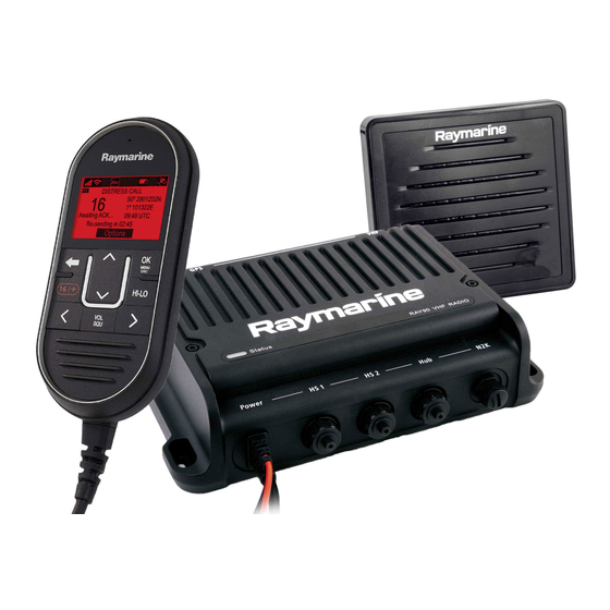
RAY91 VHF
Installation and operation instruction manual
Raymarine RAY91 VHF Installation And Operation Instruction Manual
Hide thumbs
1
2
3
4
Table Of Contents
5
6
7
8
9
10
11
12
13
14
15
16
17
18
19
20
21
22
23
24
25
26
27
28
29
30
31
32
33
34
35
36
37
38
39
40
41
42
43
44
45
46
47
48
49
50
51
52
53
54
55
56
57
58
59
60
61
62
63
64
65
66
67
68
69
70
71
72
73
74
75
76
77
78
79
80
81
82
83
84
85
86
87
88
89
90
91
92
93
94
95
96
97
98
99
100
101
102
103
104
105
106
107
108
109
110
111
112
113
114
115
116
117
118
119
120
121
122
123
124
125
126
127
128
129
130
131
132
133
134
135
136
137
138
139
140
141
142
143
144
145
146
147
148
149
150
151
152
153
154
155
156
157
158
159
160
161
162
163
164
165
166
167
168
page
of
168
Go
/
168
Contents
Table of Contents
Troubleshooting
Bookmarks
Table of Contents
Table of Contents
Chapter 1 Important Information
Certified Installation
Fcc
Compliance Statement (Part 15.19)
FCC Interference Statement (Part 15.105 (B))
Innovation, Science and Economic Development Canada (ISED)
Innovation, Sciences et Développement Économique Canada (Français)
Water Ingress
Disclaimer
Declaration of Conformity
Product Disposal
Warranty Registration
Technical Accuracy
Chapter 2 Document and Product Information
Product Documentation
Seatalkng ® Documentation
User Manuals Print Shop
Document Conventions
Document Illustrations
Product Overview
Applicable Products
Required Additional Components
Optional Wired Components
Optional Wireless Components
Compatible Mfds
Incompatible Mfds
Parts Supplied
Licensing
USA Licensing Requirements
Canada Licensing Requirements
Europe and Rest of World Licensing Requirements
Additional Information - Ray90 / Ray91
Additional Information - Wireless Handset
Additional Information - Wireless Charging Holster
Additional Information - Wireless Hub
Additional Information - Wireless Speaker
Obtain MMSI (Maritime Mobile Service Identity) Number
Automatic Transmitter Identification System (ATIS)
Software Updates
Checking Software Versions
Ray90/Ray91 Software
Performing Software Updates - Raymic Handset
Chapter 3 Installation
Selecting a Location
General Location Requirements
Antenna Mounting and EME Exposure
Multiple Antenna Installations
Loud Hailer Location Requirements
GNSS (GPS) Location Requirements
Wireless Product Location Requirements
Wireless Location Requirements
Pre-Installation Site Survey
Product Dimensions
Product Dimensions - Base Station
Product Dimensions - Speakers
Product Dimensions - Wired Handset (Raymic)
Product Dimensions - Wireless Hub
Product Dimensions - Wireless Handset and Holster
Mounting
Tools Required for Installation
Mounting the Base Station
Wired and Wireless Speaker Mounting
Wired Handset Mounting Using the Holster
Pass-Through Panel Kit Mounting
Mounting the Wireless Hub
Mounting the Charging Holster for the Wireless Handset
Chapter 4 Cables and Connections
General Cabling Guidance
Cable Types and Length
Cable Routing
Strain Relief
Circuit Isolation
Cable Shielding
Connections to Other Equipment
Dust Caps
Bare End Wire Connections
Connections Overview
Power Connection
In-Line Fuse and Thermal Breaker Ratings
Grounding
Power Distribution
Handset Station Connection
Connecting Handsets and Cables
Wired Handset Extension Cables
Wired Speaker Connection
NMEA 2000 / Seatalkng ® Connection
Connecting Seatalkng ® Cables
NMEA 0183 Connection
Loud Hailer Connection
Connecting GNSS (GPS) and VHF Antennas
Wireless Hub Connection
Wireless Handset Charging Holster - Power Connection
In-Line Fuse and Thermal Breaker Ratings
Wireless Handset Connections
Wireless Speaker - Power Connection
In-Line Fuse and Thermal Breaker Ratings
Chapter 5 Getting Started
Handset Controls
Wireless Speaker Controls
Powering the Base Station
Powering the Handset
Homescreen Overview
Status Bar Symbols
Main Menu Overview
Multiple Station Operation
Adjusting Brightness and Contrast
Shared Brightness
Enabling Shared Brightness
Initial Set up
Selecting a Language
Switching on the AIS Receiver
Selecting a Network Type
Entering Your MMSI Number
Entering Your ATIS ID
Enabling and Disabling ATIS Mode
Changing the Radio Region
Switching between High and Low Transmit Power
GNSS (GPS) Set up
Enabling and Disabling the Internal GNSS (GPS)
GNSS Data Source
No Position Data
Entering Position Manually
Selecting (GNSS) GPS Information to Display
Setting Time Format and Offset
Chapter 6 Wireless Handset Stations
Wireless Handsets
Wireless Handset Charging
Connecting a Wireless Handset to the Hub
Checking the Wireless Hub's Password
Changing Your Wireless Hub's Password
Changing the Hub's Wireless Channel
Connecting the Wireless Speaker to the Wireless Handset
Disconnecting a Wireless Speaker
Wireless Set-Up Menu Options
Wireless Hub Set-Up Menu Options
Wireless Handset Not Connected Menu
Chapter 7 Digital Selective Calling (DSC)
Digital Selective Calling (DSC)
Distress Calls
Making a Designated Distress Call
Making a Distress Call
Making a Mayday Call
Cancelling a Distress Call before Transmission
Cancelling a Distress Call after Transmission
Receiving a Distress Call
Ignoring a Distress Call
Acknowledging a Distress Call
Manually Relaying a Distress Call
Distress Relays Sent by Other Stations
Urgency Calls
Making an Urgency Call
Receiving an Urgency Call
Safety Calls
Making a Safety Call
Receiving a Safety Call
Individual (Routine) Calls
Making an Individual Call
Receiving an Individual Call
Group Calls
Making a Group Call
Receiving a Group Call
Position Requests
Making a Position Request
Responding to a Position Request
Setting Automatic Response to Position Requests
Phonebook
Adding a Phonebook Entry
Editing a Phonebook Entry
Deleting a Phonebook Entry
Call Logs
Accessing the Call Logs
Test Calls
Making a Test Call
Receiving a Test Call
DSC Set-Up Menu Options
Chapter 8 VHF Operations
Watch Modes
Setting Watch Mode
Scan Mode
Setting Scan Mode
Priority Channels
Switching between Priority Channels
Setting a Second Priority Channel
Sensitivity
Switching Sensitivity Modes
Private Channels
Selecting a Private Channel Set
Automatic Transmitter Identification System (ATIS) and Marcom-C Mode
Enabling and Disabling ATIS Mode
AIS Receiver
Switching AIS on and off
Set-Up Menu Options
Display Set-Up Menu
Shared Brightness Menu
Chapter 9 Hailer, Fog Horn, and Intercom
Hailer Fog Intercom Menu
Loud Hailer
Using the Hailer
Fog Horn
Using the Fog Horn in Manual Mode
Using Automatic Fog Horn Modes
Switching off Fog Horn Mode
Intercom
Using the Intercom
Responding to the Intercom
Chapter 10 Maintenance
Maintenance
Routine Checks
Unit Cleaning Instructions
Chapter 11 Troubleshooting
LED Diagnostics - Ray90 / Ray91 Base Station
LED Diagnostics - Wireless (Active) Speaker
Troubleshooting
Performing a System Reset
System Test
Checking for RF Interference
Power up Troubleshooting
Audio Troubleshooting (Transmission / Reception)
Passive Speaker Troubleshooting
GNSS (GPS) Troubleshooting
DSC Troubleshooting
Obtain MMSI (Maritime Mobile Service Identity) Number
AIS Troubleshooting (Ray70 / 73 / 91 Only)
Wired Handset Troubleshooting
Wireless Troubleshooting (Ray63 / 73 / 90 / 91 Only)
Chapter 12 Technical Support
Raymarine Product Support and Servicing
Viewing Product Information
Learning Resources
Chapter 13 Technical Specification
Technical Specification - Base Station
Technical Specification - Wired Handset (Raymic)
Technical Specification - Wired (Passive) Speaker
Technical Specification - Wireless Hub
Technical Specification - Wireless Handset
Technical Specification - Wireless Handset Charging Holster
Technical Specification - Wireless (Active) Speaker
Radio Usage
Chapter 14 Spares and Accessories
Ray90 / Ray91 Spares
Extension Cables
Accessories
Seatalkng ® Cables and Accessories
Appendix A NMEA 0183 Sentences
Appendix B NMEA 2000 PGN List
Appendix C MMSI Regulatory Bodies and Application Submissions
Appendix D VHF Channels
Appendix E Phonetic Alphabet
Appendix F Prowords
Advertisement
Quick Links
Download this manual
RAY90/91 VHF
Installation and operation instructions
English (en-US)
Date:
02-2020
Document number:
81377-6
© 2020 Raymarine UK Limited
Table of
Contents
Previous
Page
Next
Page
1
2
3
4
5
Advertisement
Table of Contents
Troubleshooting
Chapter 11 Troubleshooting
117
Troubleshooting
119
Power up troubleshooting
121
Audio troubleshooting (transmission / reception)
123
Passive speaker troubleshooting
124
GNSS (GPS) troubleshooting
125
DSC troubleshooting
126
AIS troubleshooting (Ray70 / 73 / 91 only)
127
Wired handset troubleshooting
128
Wireless troubleshooting (Ray63 / 73 / 90 / 91 only)
129
Need help?
Do you have a question about the RAY91 VHF and is the answer not in the manual?
Ask a question
Questions and answers
Related Manuals for Raymarine RAY91 VHF
Radio Raymarine RAY90 Installation And Operation Instruction Manual
(192 pages)
Radio Raymarine RAY90 Installation & Operation Instructions
(108 pages)
Radio Raymarine Ray50 Troubleshooting Manual
Vhf dsc radios (60 pages)
Radio Raymarine RAY91 Installation And Operation Instruction Manual
(168 pages)
Radio Raymarine RAY90 VHF Installation And Operation Instruction Manual
(168 pages)
Radio Raymarine RAY230E Owner's Handbook Manual
Fixed mount (150 pages)
Radio Raymarine Ray54 Owner's Handbook Manual
Raymarine owner's handbook marine vhf radio ray54 (112 pages)
Radio Raymarine Ray215 Owner's Handbook Manual
Modular vhf radio (134 pages)
Radio Raymarine Ray101 Owner's Handbook Manual
Handheld vhf radio (62 pages)
Radio Raymarine Ray240 User Manual
Vhf radio with digital selective calling (78 pages)
Radio Raymarine Ray240 User Manual
With digital selective calling (72 pages)
Radio Raymarine RAY 240 Manual
Vhf radio (20 pages)
Radio Raymarine Ray55E Owner's Handbook Manual
Marine vhf radio (128 pages)
Radio Raymarine Ray 410 User Manual
Raymarine ray 410: user guide (46 pages)
Radio Raymarine Ray430 Operation Manual
Loudhailer (59 pages)
Radio Raymarine Ray 53 User Manual
Raymarine ray 53: user guide (47 pages)
This manual is also suitable for:
Ray90 vhf
382047
382048
Table of Contents
Print
Rename the bookmark
Delete bookmark?
Delete from my manuals?
Login
Sign In
OR
Sign in with Facebook
Sign in with Google
Upload manual
Upload from disk
Upload from URL


Need help?
Do you have a question about the RAY91 VHF and is the answer not in the manual?
Questions and answers