Table of Contents
Advertisement
Quick Links
No. CP-SP-1074E
FRS100
Multiburner Control
User's Manual
Thank you for purchasing the FRS100
Multiburner Control.
This manual contains information for
ensuring the correct use of the FRS100.
It also provides necessary information
for installation, maintenance, and trou-
bleshooting.
This manual should be read by those
who design and maintain equipment
that uses the FRS100. Be sure to keep
this manual nearby for handy reference.
Advertisement
Table of Contents

Related Manuals for Yamatake azbil FRS100


Summary of Contents for Yamatake azbil FRS100
- Page 1 No. CP-SP-1074E FRS100 Multiburner Control User's Manual Thank you for purchasing the FRS100 Multiburner Control. This manual contains information for ensuring the correct use of the FRS100. It also provides necessary information for installation, maintenance, and trou- bleshooting. This manual should be read by those who design and maintain equipment that uses the FRS100.
- Page 2 If you should find an error or omis- sion, please contact Yamatake Corporation. In no event is Yamatake Corporation liable to anyone for any indirect, special or consequential damages as a result of using this product.
- Page 3 SAFETY PRECAUTIONS ■ About Icons The safety precautions described in this manual are indicated by various icons. Please be sure you read and understand the icons and their meanings described below before reading the rest of the manual. Safety precautions are intended to ensure the safe and correct use of this prod- uct, to prevent injury to the operator and others, and to prevent damage to proper- ty.
- Page 4 WARNING Before removing, mounting or wiring the FRS100, be sure to turn the power OFF. Failure to do so might cause electric shock. Do not touch the terminals on this control. Doing so might result in an electric shock. This control is for batch operation (at least one start and stop in 24 hours of operation) that utilizes the start check function.
- Page 5 WARNING After the pilot turndown test is completed, turn the power switch OFF to turn the power OFF. Be sure to restore all test jumper leads, limit switches and control settings used in the test to their original settings. If this control is operated without these components restored, it might be damaged, or a gas leak or explosion might result.
- Page 6 CAUTION Be sure to wire the power supply last of all. Touching terminals by mistake with the power ON might cause an electric shock or malfunction. Make sure that the loads connected to the terminals do not exceed the specified ratings. Make sure that power of the same voltage and frequency as indicated on the model number label is supplied to the control.
- Page 7 Conventions Used in This Manual The following conventions are used in this manual: Handling Precautions Handling Precautions indicate items that the user should pay attention to when handling the FRS100. Note Notes indicate information that might benefit the user. (1), (2), (3): Numbers within parentheses indicate steps in a sequence or parts of an explanation.
-
Page 8: Table Of Contents
SAFETY PRECAUTIONS Conventions Used in This Manual Chapter 1. OVERVIEW AND PRODUCT CONFIGURATION ■ Overview.......................1-1 ■ Features......................1-1 ■ Model listing....................1-1 ■ Names of parts.....................1-2 ■ Configuration ....................1-2 Chapter 2. MOUNTING AND WIRING 2-1 Mounting and Wiring the Subbase..............2-1 2-2 Wiring........................2-4 ■... -
Page 9: Overview
C h a p t e r 1 . O V E R V I E W A N D P R O D U C T C O N F I G U R A T I O N O v e r v i e w The FRS100 Multiburner Control features built-in safe-start circuitry. -
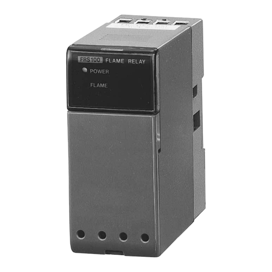
Page 10: Names Of Parts
Chapter 1. OVERVIEW AND PRODUCT CONFIGURATION ■ Names of parts ● FRS100 body ● FRS50A100 subbase (sold separately) ■ Configuration ● Flame Detector FRS100B FRS100C Name Model No. Name Model No. Ultraviolet Flame Detector C7012A/C Minipeeper Ultraviolet Flame C7035A, C7027A Detector C7007A, C7008A Flame Rod... -
Page 11: Chapter 2. Mounting And Wiring
Chapter 2. MOUNTING AND WIRING 2 - 1 Mounting and Wiring the Subbase CAUTION Do not mount this control in the following locations: • Near corrosive chemicals or gases (ammonia, sulfur, chlorine, ethylene compounds, acid, etc.) • Where subject to water spray or extreme humidity •... - Page 12 Chapter 2. MOUNTING AND WIRING ● Mounting direction • Mount so that the arrow on the subbase is facing upwards. • Mount so that the display panel is in front. ● DIN rail mounting (1) Pull the DIN rail fixing plate downwards. (2) Place the controller on the DIN rail so that the arrow on the subbase is facing upwards.
- Page 13 Chapter 2. MOUNTING AND WIRING ● Direct panel mounting (1) Drill two M4 mounting holes in the panel so that the arrow on the subbase will be facing upward. M4 (2 locations) (2) Attach the two mounting holes on the subbase to the panel using two M4 screws at a maximum torque of 0.7N •...
-
Page 14: Wiring
Chapter 2. MOUNTING AND WIRING 2 - 2 Wiring WARNING Wire external leads between the power supply terminals (100V, or 200V and 0V) of this control so that power is supplied at all times from the moment the power switch is turned ON. This wiring is necessary to ensure operation of the self-test circuits at startup. -
Page 15: Wiring Overview
Chapter 2. MOUNTING AND WIRING ■ Wiring overview ● Manual ignition (intermittent pilot) Handling Precautions • The power supply is marked H and G for the voltage and ground sides, respectively. Accordingly, connect the voltage side (H) to terminal 1 and the ground side (G) to terminal 2. -
Page 16: Wiring The Flame Detector
Chapter 2. MOUNTING AND WIRING ■ Wiring the flame detector CAUTION Connect the blue signal lead from the Minipeeper Ultraviolet Flame Detector to terminal 5 (F) and the white lead to terminal 6 (G). If the power is turned ON with these leads miswired, the built-in UV tube may be damaged. ●... -
Page 17: Wiring The Solenoid Valve
Chapter 2. MOUNTING AND WIRING ■ Wiring the solenoid valve CAUTION Do not connect the solenoid valve to the voltage side. If a ground fault occurs, ground current will flow to the solenoid valve and open it, causing fuel to flow regardless of the state of this control. ●... -
Page 18: Wiring The Surge Absorber
Chapter 2. MOUNTING AND WIRING ■ Wiring the surge absorber Wire as shown below when using a surge absorber (model No.83968019-001, ordered separately) for protection from lightning surge. Handling Precautions • Use a JIS C 3306, 0.75mm power lead (lead diameter 0.18, 30-strand) or higher for wiring to the power supply. -
Page 19: Chapter 3. Explanation Of Operation
C h a p t e r 3 . E X P L A N A T I O N O F O P E R A T I O N M a n u a l i g n i t i o n ( I n t e r m i t t e n t p i l o t ) •... - Page 20 Chapter 3. EXPLANATION OF OPERATION ● Operation Operation FRS100 Operation Equipment State Power switch ON, • Power is applied across the 100V or 200V and 0V limit switch ON power terminals on the equipment (the POWER LED lights up). Operation contact ON • Start check is carried out by energizing terminal 7, Ready for ignition.
-
Page 21: Burner Flame Monitoring
Chapter 3. EXPLANATION OF OPERATION ■ Burner flame monitoring Normal Operation [Input] Operation input (terminals 1-7) Flame detection F-G (terminals 5-6) [Output] Start check output (terminals 3-8) Flame output (terminals 3-4) [Indication] Flame failure response POWER LED FLAME LED 2K Start check LED False Flame Operation [Input]... -
Page 22: Chapter 4. Adjustments For Trial Operation
Chapter 4. ADJUSTMENTS FOR TRIAL OPERATION WARNING Prevent the pilot and main burner ignition times from exceeding the burner ignition time which the equipment manufacturer specifies. Excessively long ignition time might cause fuel to accumulate in the combustion chamber and an explosive air-fuel mix to form, resulting in the risk of a serious explosion. -
Page 23: How To Measure The Flame Signal
Chapter 4. ADJUSTMENTS FOR TRIAL OPERATION • Disconnect the loads and flame detector wiring. Measure the insulation resistance across the terminals and panel ground, and make sure that the resistance is 50MΩ or more using an insulation tester or megger of 500Vdc or more. -
Page 24: Pilot Turndown Test
Chapter 4. ADJUSTMENTS FOR TRIAL OPERATION ■ Pilot turndown test This test is for checking that the pilot flame is transferred to the main burner when the flame detector detects the pilot flame, even if gas pressure and air pressure are at their worst. - Page 25 Chapter 4. ADJUSTMENTS FOR TRIAL OPERATION (6) Slowly open the manual valve for the pilot until the pressure matches the pressure immediately before the combustion lamp went out. Then, press the ignition switch again to ignite the pilot. (7) Release the ignition switch. Make sure that the main burner ignites without any problem in one second or less when the main burner manual valve is opened.
-
Page 26: Ignition Spark Response Test
Chapter 4. ADJUSTMENTS FOR TRIAL OPERATION ■ Ignition spark response test This test should be carried out on any equipment that uses an ultraviolet flame detector. The test is to check whether or not the ultraviolet flame detector responds to UV rays emitted from the ignition spark. ●... -
Page 27: Safety Shutoff Test
Chapter 4. ADJUSTMENTS FOR TRIAL OPERATION ● Cautions Regarding UV Sources Other Than Flames The table below shows sources other than flames that emit UV rays that can be detected by the ultraviolet flame detector. Make sure that these UV sources do not influence operation of the ultraviolet flame detector under any operating conditions. -
Page 28: Chapter 5. Maintenance And Inspection
Chapter 5. MAINTENANCE AND INSPECTION WARNING Before removing or mounting the FRS100, be sure to turn the power OFF. Failure to do so might cause electric shock. Do not touch the terminals on this control. Doing so might result in an electric shock. -
Page 29: Troubleshooting
Chapter 5. MAINTENANCE & INSPECTION ■ Troubleshooting If a problem occurs, remove the front cover of the controller. Determine the operating state of the controller and type of trouble by checking the start check, POWER and FLAME LED display states. The start check LED is located in the center inside the cover, and the POWER and FLAME LEDs are located on the front display. -
Page 30: Chapter 6. Specifications
Chapter 6. SPECIFICATIONS ■ Specifications Rated Power Supply 100Vac 50 / 60 Hz 200Vac 50 / 60 Hz Allowable Voltage -15 to +10% of rated voltage Power Consumption 7W max. Contact Rating 250Vac (across terminals 3-4, 3-8) Flame Sensitivity Ignition detection level: Flame voltage: 1V max. -
Page 31: External Dimensions
Chapter 6. SPECIFICATIONS ■ External dimensions ● External dimensions when FRS100 is mounted on FRS50A100 (Unit: mm) DIN rail Subbase (FRS50A100, sold separately) FRS100 Cover *1. Dimensions required for mounting and removing body *2. Dimensions required for mounting and removing from DIN rail... - Page 32 Chapter 6. SPECIFICATIONS ● FRS50A100 subbase M3.5 terminal screw (8) DIN rail Subbase mounting holes (2) DIN rail mounting plate...
- Page 33 R e v i s i o n H i s t o r y P r i n t e d M a n u a l N u m b e r E d i t i o n R e v i s e d p a g e s D e s c r i p t i o n d a t e...
- Page 34 Specifications are subject to change without notice. Advanced Automation Company 1-12-2 Kawana, Fujisawa Kanagawa 251-8522 Japan Printed in Japan. URL: http://www.azbil.com 1st Edition: Issued in Oct. 1999 (K) 13th Edition: Issued in Jan. 2007 (U) Printed on recycled paper. (07)
Need help?
Do you have a question about the azbil FRS100 and is the answer not in the manual?
Questions and answers