
Related Manuals for Kracht VOLUMEC AVC 02.1


Summary of Contents for Kracht VOLUMEC AVC 02.1
- Page 1 D.0030390002 Operating instructions (Translation) VOLUMEC Valve Position Indicator 02/04 88030390002-03 Englisch 2022-07-08...
-
Page 2: Table Of Contents
Table of Content General About the documentation Manufacturer´s address Intended use Safety Symbolism Personnel qualification and training Basic safety instructions Warning Device description Basic construction and function Basic design 3.2.1 Indicator AVC 02.1 3.2.2 Indicator AVC 02.4 3.2.3 3.2.4 HB 4.0311. 3.2.5 HB 4.0324. - Page 3 General Electrical connection Operation start-up Safety instructions for start-up Further operation start-up Permissible limits for operation Removal General Removing the device Technical data General Unusual noise Static seals Screw joints Surface temperature Repairs 10.1 General 10.2 Troubleshooting 10.3 Elimination of damage 10.4 Return 10.5...
-
Page 4: General
4 “Technical data”. If you have any questions about this operating manual, please contact the manufacturer. 1.2 Manufacturer´s address KRACHT GmbH Gewerbestraße 20 DE 58791 Werdohl phone: +49 2392 935-0 fax: +49 2392 935-209 email: info@kracht.eu web: www.kracht.eu... - Page 5 VOLUMEC Valve Position Indicator 02/04 ○ intended use, ○ conscious of safety and danger, taking the operating instructions into account. The device may only be used when it is in a proper condition. Deviations from the operating conditions require express approval by the manufacturer.
-
Page 6: Safety
VOLUMEC Valve Position Indicator 02/04 2 Safety 2.1 Symbolism DANGER Identification of an immediate hazard, which would result in death or severe bodily injury if not avoided. WARNING Identification of a potential medium risk hazard, which would lead to death or severe bodily injury if not avoided. CAUTION Identification of a low risk hazard, which could lead to minor or medium bodily injury if not avoided. -
Page 7: Basic Safety Instructions
VOLUMEC Valve Position Indicator 02/04 2.3 Basic safety instructions Comply with existing regulations on accident prevention and safety at work along with any possible internal operator regulations. Pay attention to the greatest possible cleanliness. Wear suitable personal protection equipment. Do not remove, make illegible or obliterate type plates or other referen- ces on the device. - Page 8 VOLUMEC Valve Position Indicator 02/04 WARNING Hazard due to pressurized parts Danger of injury from spurting fluids. Depressurize the connection lines and keep the connection lines dep- ressurised during all work on the device. Wear suitable protective equipment. WARNING Failure of load-carrying parts due to overload! Danger of injury from flying parts.
-
Page 9: Device Description
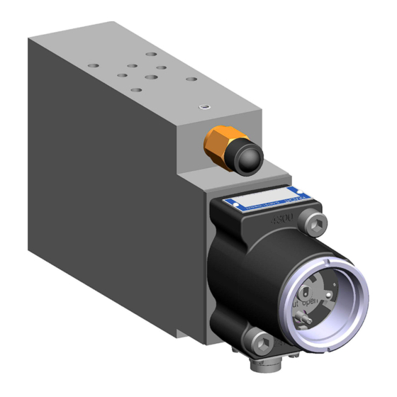
VOLUMEC Valve Position Indicator 02/04 3 Device description 3.1 Basic construction and function The device is operated together with a type VCM volumetric meter and by type HB 4 hydraulic block. The VCM hydraulically records the movement of an actuator and transmits it using a permanent-magnetic coupling to the device gearbox. -
Page 10: Basic Design
VOLUMEC Valve Position Indicator 02/04 3.2 Basic design 3.2.1 Indicator AVC 02.1 Description 10. Gear housing 70. Male socket 20. Cover 80. Contact plate 30. Indicator glass 90. Contact pointer 40. Measuring gear 100. Indicator signal 50. Magnet 110. O-Ring 60. Potentiometer 120. - Page 11 VOLUMEC Valve Position Indicator 02/04 3.2.2 Indicator AVC 02.4 Description 10. Gear housing 70. Male socket 20. Cover 80. Contact plate 30. Indicator glass 90. Contact pointer 40. Measuring gear 100. Indicator signal 50. Magnet 110. O-Ring 60. Potentiometer 120. Seal 88030390002-03 2022-07-08...
-
Page 12: Vcm
VOLUMEC Valve Position Indicator 02/04 3.2.3 VCM Description 10. Housing 60. Bearing pin 20. Cover 70. Magnet 30. Gear 80. Socket head cap screw 40. Plain bearing bush 90. O-Ring 50. Plain bearing bush 100. O-Ring 2022-07-08 88030390002-03... - Page 13 VOLUMEC Valve Position Indicator 02/04 3.2.4 HB 4.0311. Description 10. Housing 80. Draw spring 20. Change-over piston 90. Screw plug 30. Valve cone 100. Flow restrictor 40. Guide sleeve 110. Flow-control screw 50. Compression spring 120. Expander plugs 60. Excess-pressure valve 130.
- Page 14 VOLUMEC Valve Position Indicator 02/04 3.2.5 HB 4.0324. Description 10. Housing 60. Screw plug 20. Compression spring 70. Flow restrictor 30. Excess-pressure valve 80. Flow-control screw 40. Anti-cavitation valve 90. Expander plugs 50. Draw spring 100. O-Ring 2022-07-08 88030390002-03...
-
Page 15: Type Key
5. Electrical connection without elektric Attaching plug Series 723 5-pin (Standard) Attaching plug DIN EN 175301-803 KEMA-acceptance (old DIN 43650) 6. Design serial number (specified by manufacturer) 7. Transmission gears e.g. U 98.3:1 (will be selected by KRACHT) 88030390002-03 2022-07-08... -
Page 16: Volume Counter Vcm
VOLUMEC Valve Position Indicator 02/04 3.3.2 Volume counter VCM Ordering example Explanation of type key 1. Product name 2. Nominal size 3. Seal 4. Construction type EN-GJL-250 / AL Brass CW710R/2.0540 AL ENAW-6082 (seawater resistant) 5. Type of connection Plate structure 6. -
Page 17: Valve Block Hb
VOLUMEC Valve Position Indicator 02/04 3.3.3 Valve block HB 4 Ordering example HB 4 0311 Explanation of type key 1. Product name 2. Construction type 3. Function 0311 0324 4. Design serial number (specified by manufacturer) 5. Temperature-specific pressure limitation = 110 bar = 240 bar = 180 bar 6. -
Page 18: Technical Data
VOLUMEC Valve Position Indicator 02/04 4 Technical data 4.1 General information General information VOLUMEC Hole pattern / Nominal size ISO 4401 / DIN 24340-A6 Connection type Connection plate (not included in the scope of delivery) Mounting position Ambient temperature -20°C ... +60°C 4.2 Hydraulic parameters Hydraulic parameters VOLUMEC Geom. -
Page 19: Electrical Parameters
VOLUMEC Valve Position Indicator 02/04 4.3 Electrical parameters Electrical data Conductive plastic potentiometer Connection resistance 1 kΩ Resistance tolerance ± 20% Linearity ± 2% Max. wiper current 1 mA Power rating 0.2 W / 55°C Dielectric strength 500 V / 1 min Isolation resistance >... -
Page 20: Dimensions
VOLUMEC Valve Position Indicator 02/04 4.4 Dimensions Dimensions of the device can be found in the relevant technical data sheets. 2022-07-08 88030390002-03... -
Page 21: Transport And Storage
VOLUMEC Valve Position Indicator 02/04 5 Transport and storage 5.1 General ● After receipt, check the device for transport damages. ● If transport damage is noticed, report this immediately to the manufac- turer and the carrier. The device must then be replaced or repaired. ●... -
Page 22: Installation
VOLUMEC Valve Position Indicator 02/04 6 Installation 6.1 General WARNING Hazard due to pressurized parts Danger of injury from spurting fluids. Depressurize the connection lines and keep the connection lines dep- ressurised during all work on the device. Wear suitable protective equipment. 6.2 Electrical connection Compliance with the maximum permissible operating pressures of the po- tentiometer listed in the... -
Page 23: Operation Start-Up
VOLUMEC Valve Position Indicator 02/04 7 Operation start-up 7.1 Safety instructions for start-up DANGER Hazardous fluids! Danger of death when handling hazardous fluids. Comply with the safety data sheets and regulations on handling haz- ardous fluids. Collect and dispose of hazardous fluids so that no hazards arise for people or the environment. -
Page 24: Removal
VOLUMEC Valve Position Indicator 02/04 8 Removal 8.1 General DANGER Danger when dismantling the valve cap The valve cover stands under high spring pressure. Parts flying around uncontrolled or fluids squirting out lead to accidents with severe injuries or even result in death. The removal of the valve or the valve cover is not allowed. -
Page 25: Removing The Device
VOLUMEC Valve Position Indicator 02/04 8.2 Removing the device DANGER Exposed electrical components! Danger of death due to electric shock. Follow the special safety regulations during all work on electrical instal- lations. Only allow electricians to work on electrical systems. Only use connection lines that are resistant to ambient influences and media. -
Page 26: Technical Data
VOLUMEC Valve Position Indicator 02/04 9 Technical data The technical data of the device can be found in the order-related documents. 9.1 General NOTICE Property damage and malfunctions If the device is not regularly maintained, damage that is not discovered or not repaired can lead to malfunctions and to the failure of the device. Maintain and clean the device regularly. -
Page 27: Unusual Noise
VOLUMEC Valve Position Indicator 02/04 DANGER Device can burst if pressure is too high! Parts flying around uncontrolled or squirting fluids can lead to accidents with severe injuries or even lead to death. Use only connections and lines approved for the expected pressure range. -
Page 28: Screw Joints
VOLUMEC Valve Position Indicator 02/04 If there are any visible leaks, immediately stop plant operation. If the leaks cannot be stopped by simply retightening the connection, replace all affected seals. 9.4 Screw joints All the screw joints must be checked at regular intervals to make sure they are tight fit. -
Page 29: Repairs
VOLUMEC Valve Position Indicator 02/04 10 Repairs 10.1 General The repairs covers: Troubleshooting Determination of damage, pinpointing and localisation of the damage cause. Elimination of damage Elimination of the primary causes and replacement or repair of defective components. The repair is generally made by the manufacturer. Repairs by manufacturer ●... -
Page 30: Troubleshooting
VOLUMEC Valve Position Indicator 02/04 Repair by equipment builder/operator If corresponding expertise and sufficient equipment is available, the equip- ment builder/operator can also make the repairs. Please consult the manu- facturer about this. ● If required, request spare parts lists and assembly drawings from the manufacturer. -
Page 31: Return
VOLUMEC Valve Position Indicator 02/04 10.4 Return If the device has to be repaired or checked over the manufacturer's permises, ist must be packed suitably for transport. In addition, a safety data sheet for the medium used must be enclosed with the device. In case of well-known mineral oils, at least the exact type description is required. - Page 32 VOLUMEC Valve Position Indicator 02/04 Failure Potential causes Possible measures Leakage display (indicator) ro- Internal leaks Have the unit repaired or re- tates even though the actuator is placed by the manufacturer. in the "shut" or "open" end posi- tion Contact pointer does not move Gear friction coupling re- Have manufacturer readjust the...
-
Page 33: Appendix
VOLUMEC Valve Position Indicator 02/04 11 Appendix 88030390002-03 2022-07-08...
Need help?
Do you have a question about the VOLUMEC AVC 02.1 and is the answer not in the manual?
Questions and answers