Table of Contents
Advertisement
Advertisement
Table of Contents

Related Manuals for Kracht AS 8


Summary of Contents for Kracht AS 8
- Page 1 O p e r a t i n g I n s t r u c t i o n s Volutronic...
- Page 2 PAGE 2 BAS8-02.02-GB...
-
Page 3: Table Of Contents
1. SAFETY 2. DESCRIPTION 3. CONNECTING THE AS8 3.1 Connecting the voltage supply 3.2 Connecting the volume counter 3.2.1 How is the flow rate measurement activated ? 3.2.2 How is the volume measurement activated ? 3.3 Connecting the relay contacts 3.4 Connecting the analogue outputs 3.5 Connecting the printer 3.5.1 Which data can be printed out ? -
Page 4: Safety
1. Safety The safety notes included in these operating instructions are indicated by this ‘attention-getter’ symbol. If the text accompanying this symbol is not heeded, danger to personnel or equipment may result. Other instructions, which are not safety warnings, but which give advice on optimum operation, are indicated by a hand. -
Page 5: Description
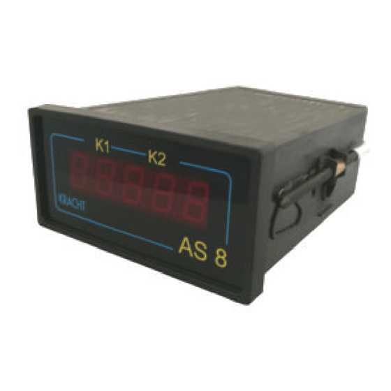
Measuring equipment devices in the AS8 series are four segment indicator units for flow rate and volumetric measurement. The units are usually operated in conjunction with KRACHT volume counters. However, other measuring systems with incremental signals can be connected. These may, for example, be oval wheel meters or angle of rotation sensors. -
Page 6: Connecting The As8
115 and 230 Volt. 3.2 Connecting the volume counter The AS8 is preferably operated in conjunction with KRACHT volume counters. However, other measuring systems with incremental signals can be connected. These can be, for example, oval wheel meters or angle of rotation sensors. - Page 7 Sensor supply The sensor supply is not short circuit proof. The sensor supply is connected to connections 8 and 9. However, the sensor supply must not be used for the supply of unearthed inductances or capacitive loads. Voltage Ripple Maximum permissible current Terminal 8 +24 VDC +/- 20 % load dependent...
-
Page 8: How Is The Flow Rate Measurement Activated
3.2.1 How is the flow rate measurement activated ? As soon as a medium flows through the volume counter a flow rate indication appears. No special action is required. The instantaneous flow rate is indicated, as a rule in litres per minute. The AS8 must be adjusted to the actual volume counter that is connected. -
Page 9: Connecting The Relay Contacts
3.3 Connecting the relay contacts The AS8 has two relay contacts. The relays are designed as potential-free contacts. That is to say, the user must input the potential at the base terminal. The relays are provided with normally-open contacts. The switching voltage is 24 V, maximum switching current is 1A. -
Page 10: Connecting The Analogue Outputs
3.4 Connecting the analogue outputs The AS8 operates via an analogue output or a serial interface. The appropriate adjustment is achieved within the device, by means of jumpers. The jumper settings for current output and voltage output are shown in the accompanying figures. Current output setting JP2 JP1 P3 JP4... - Page 11 How does the analogue output function ? The function of the analogue output can be freely selected, i.e. it can be assigned to the measurement parameters of flow rate or volume. The display, the relay and the analogue output can be switched to flow rate measurement or volume measurement , as required.
-
Page 12: Connecting The Printer
3.5 Connecting the printer The AS8 makes use of a serial interface having an RS232 layout. The choice between analogue output or serial interface is made by means of a jumper inside the unit. Setting for the serial interface JP2 JP1 P3 JP4 P2 P1 The RS232 has the fixed setting: 9600 baud, 8 bit, No parity, XON, XOFF. -
Page 13: Parameterising Via The Serial Interface
3.6 Parameterising via the serial interface A PC or a PLC is connected to the AS8 via the serial interface. The PC or PLC can change specific AS8 parameters by means of an ASCII character string. The unit distinguishes between the different values through an identifying letter. No protocol is used. -
Page 14: As8 Programming
4. AS8 programming Each time the AS8 is to be operated, it is necessary to adapt the unit to the volume counter that is connected. Input procedure: The input procedure is the same for all input values and is therefore described once only. -
Page 15: Overview Of The Input Values
4.1 Overview of the input values The values which are required to be set can be inserted in the column labelled “Input value-User”. Menu - Standard Input value - Function Reference setting User 0.040 Pulse volume of volume counter 4.000 Maximum value Analogue output 0001. -
Page 16: What Must Be Programmed When Connecting A Volume Counter
This is carried out under menu reference “00 - pulse volume volume counter” and under menu reference “08” at the position “counter input”. The pulse volumes for KRACHT Volume counters can be obtained from the Table. The “X” characters in the “Input value Menu reference 08“ column are of no significance in setting the volume counter. -
Page 17: Which Display Parameters Can Be Represented (Dip Switches)
4.3 Which display parameters can be represented (DIP switches) ? The physical parameters “l/h“, “l/m“, “l/s“ and “Usgal/h“, “Usgal/m“, “Usgal/s“ can be set as display units. Switching between the display parameters is achieved using the DIP switches. The DIP switches are located behind the front cover. Setting the volume: SW 1 Function... -
Page 18: How Is The Display Set
4.4 How is the display set ? The display can be set for flow rate measurement or volume measurement. Flow rate measurement A “0” is entered at the position designated “Display” under the menu reference “07” (see 4.1 Overview of the input values). Filter function The measuring principle applied to the AS8 is that of ‘period of oscillation’. -
Page 19: What Must Be Programmed When Connecting The Relay Outputs
4.5 What must be programmed when connecting the relay outputs ? The relay function is selectable. A relay can be allocated to flow rate or volume measurement. Flow rate measurement A “0” is inserted under the menu reference “07”. This takes place at the position designated “Relay 1”... -
Page 20: What Must Be Programmed When Connecting The Analogue Output
4.6 What must be programmed when connecting the analogue output ? The function of the analogue output is selectable. The analogue output can be assigned to flow rate or volume measurement. Flow rate measurement A “0” is entered under menu reference “7”. This takes place at the position designated “Analogue output”... -
Page 21: Technical Data
5. Technical Data PIC 17C42 Processor Power pack Supply 230 V AC, +6% ... -10% / 50-60 Hz, optional 115 V AC Power consumption ca. 3.5 W Sensor supply 24 V DC +/- 20%, 50 mA General data Principle : 7 Segment LED, 13.2 mm, red Display Display :0.000 ... -
Page 22: Type Code
Ratio control loop Flow rate and ratio measurement Volume ratio measurement Sum measurement Difference measurement FM20 Flow rate measurement switchable for all KRACHT volume counters Without - Standard Flow rate or volumetricmeasurement specification 230 VAC 50/60 Hz 120 VAC 50/60 Hz... -
Page 23: Connections
7. Connections The electrical connections are made on plugable screw terminals. Stranded connections on the basis of the prevention of accidental contact in accordance with VDE 0411 Part 100 only by means of connector sleeves with insulating material caps. Non-factory wired connections should not be otherwise connected. -
Page 24: Setting The Supply Voltage
8. Setting the supply voltage Supply voltage 230 V AC/ 50-60 Hz View of circuit board from below Close solder jumper 1 to 3 supply voltage 115 V AC/ 50-60 Hz View of circuit board from below Close solder bridges 1 to 2 and 3 to 4 PAGE 24 BAS8-02.02-GB... -
Page 25: Dimensions
9. Dimensions BAS8-02.02-GB Page 25... -
Page 26: As8 As 19" Rack Unit
10. AS8 as 19“ Rack Unit The AS8 is built into a 3HE 25TE 19” front plate. All the connections for the AS8 are wired on a Eurocard and are available on a 32 pin contact strip for further connection. AS8 wiring on the contact strip: Contact PIN AS8 terminal... -
Page 27: As8 In The Desk-Top Housing
11. AS8 in the Desk-top Housing The desk-top housing is available with analogue output or serial interface. View: BAS8-02.02-GB Page 27... - Page 28 Connections with RS232 serial interface: Connections with analogue output: PAGE 28 BAS8-02.02-GB...
Need help?
Do you have a question about the AS 8 and is the answer not in the manual?
Questions and answers