
Related Manuals for BINMASTER VF-95


Summary of Contents for BINMASTER VF-95
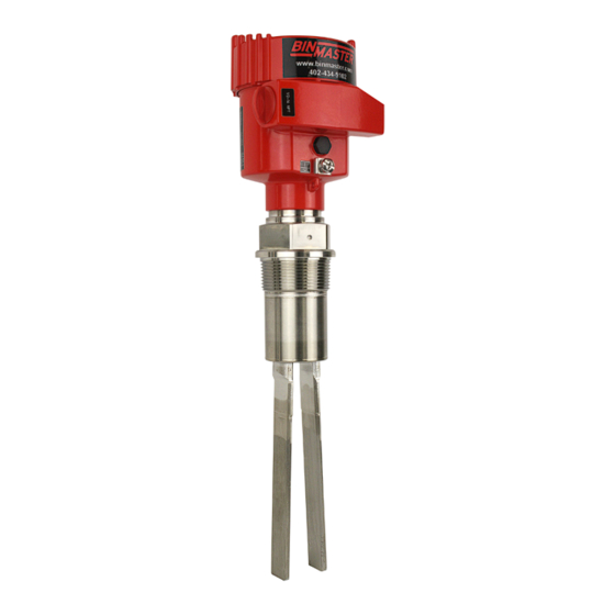
- Page 1 Operating Instructions Vibrating level switch for powders VF-95 VIBRATING FORK Document ID: 32246 925-0376...
-
Page 2: Table Of Contents
How to proceed if a repair is necessary ................24 Dismount..........................26 Dismounting steps......................26 Disposal ......................... 26 Supplement ..........................27 Technical data ........................ 27 Dimensions ........................30 Industrial property rights ....................32 Trademark ........................32 925-0376 VF-95 • Vibrating Fork... - Page 3 Contents Safety instructions for Ex areas Take note of the Ex specific safety instructions for Ex applications. These instructions are attached as documents to each instrument with Ex approval and are part of the operating instructions. Editing status: 2018-11-22 925-0376 VF-95 • Vibrating Fork...
-
Page 4: About This Document
Action This arrow indicates a single action. Sequence of actions Numbers set in front indicate successive steps in a procedure. Battery disposal This symbol indicates special information about the disposal of bat- teries and accumulators. 925-0376 VF-95 • Vibrating Fork... -
Page 5: For Your Safety
During work on and with the device, the required personal protective equipment must always be worn. Appropriate use The VF-95 is a sensor for point level detection. You can find detailed information about the area of application in chapter "Product description". Operational reliability is ensured only if the instrument is properly used according to the specifications in the operating instructions manual as well as possible supplementary instructions. -
Page 6: Safety Label On The Instrument
That is why we have introduced an environment management system with the goal of continuously improving company environmental pro- tection. The environment management system is certified according to DIN EN ISO 14001. Please help us fulfil this obligation by observing the environmental instructions in this manual: • Chapter "Packaging, transport and storage" • Chapter "Disposal" 925-0376 VF-95 • Vibrating Fork... -
Page 7: Product Description
"www.vega.com", "Search". Y ou can find the serial number on the inside of the instrument as well as on the type label on the outside. Principle of operation Application area VF-95 is a point level sensor with tuning fork for point level detection. 925-0376 VF-95 • Vibrating Fork... -
Page 8: Adjustment
Solid detection in water If VF-95 was ordered for solids detection in water, the tuning fork is set to the density of water. In air or when immersed in water (density: 1 g/cm³/0.036 lbs/in), If VF-95 signals "uncovered". Only when the vibrating element is also covered with solids (e.g. - Page 9 Technical data - Ambient conditions" • Relative humidity 20 … 85 % Lifting and carrying With instrument weights of more than 18 kg (39.68 lbs) suitable and approved equipment must be used for lifting and carrying. 925-0376 VF-95 • Vibrating Fork...
-
Page 10: Mounting
DIN/EN/IEC/ANSI/ISA/UL/CSA 61010-1. Switching point In general, If VF-95 can be installed in any position. The instrument only has to be mounted in such a way that the vibrating element is at the height of the desired switching point. -
Page 11: Mounting Instructions
Mounting instructions Mounting socket The vibrating element should protrude into the vessel to avoid buildup. For that reason, avoid using mounting bosses for flanges and screwed fittings. This applies particularly to use with adhesive products. Filling opening Mount the instrument in such a way that the tuning fork does not protrude directly into the filling stream. 925-0376 VF-95 • Vibrating Fork... - Page 12 A spout forms in the concave protective sheet preventing wear of the protective sheet. Horizontal mounting To achieve a very precise switching point, you can install VF-95 horizontally. However, if the switching point can have a tolerance of a few centimeters, we recommend mounting VF-95 approx. 20° inclined to the vessel bottom to avoid buildup.
- Page 13 4 Mounting VF-95 at a position in the vessel where no disturbances, e.g. from filling openings, agitators, etc., can occur. Product flow To make sure the tuning fork of VF-95 generates as little resistance as possible to product flow, mount the sensor so that the surfaces are parallel to the product movement. Fig. 5: Flow orientation of the tuning fork...
- Page 14 4 Mounting > 125 mm (> 5") Fig. 7: Baffle for protection against mechanical damage 925-0376 VF-95 • Vibrating Fork...
-
Page 15: Connecting To Power Supply
In hazardous areas, use only approved cable connections for VR-95. Take note of the corresponding installation regulations for Ex Connection cable applications. for Ex applications Cover all housing openings conforming to standard according to EN 60079-1. 925-0376 VF-95 • Vibrating Fork... -
Page 16: Connection Procedure
10. If necessary, carry out a fresh adjustment 11. Screw the housing lid back on The electrical connection is finished. Wiring plan, single chamber housing The following illustrations apply to the non-Ex as well as to the Ex-d version. 925-0376 VF-95 • Vibrating Fork... - Page 17 Stainless steel, electropolished (not with Ex d) Filter element for pressure compensation (not with Ex d) Wiring plan We recommend connecting VF-95 in such a way that the switching circuit is open when there is a level signal, line break or failure (safe state).
- Page 18 5 Connecting to power supply Fig. 10: Wiring plan Shielding 925-0376 VF-95 • Vibrating Fork...
-
Page 19: Setup
(1) It is already preset and must only be modified in special cases. By default, the potentiometer of VF-95 is set to the right stop (> 0.02 g/cm³ or 0.0008 lbs/in³). In case of very light-weight solids, turn the potentiometer to the left stop (> 0.008 g/cm³ or 0.0003 lbs/ 925-0376 VF-95 •... -
Page 20: Function Table
6 Setup in³). VF-95 will thus be more sensitive and can detect light-weight solids more reliably. For instruments detecting solids in water, these settings are not ap- plicable. The density range is preset and must not be changed. Mode adjustment (2) With the mode adjustment (min./max.) you can change the switching... - Page 21 6 Setup Level Switching status Control lamp Fault Switch open flashes red 925-0376 VF-95 • Vibrating Fork...
-
Page 22: Maintenance And Fault Rectification
These may be caused by the following, e.g.: • Sensor • Process • Voltage supply • Signal processing The first measure to take is to check the output signal. In many cases, Fault rectification the causes can be determined this way and the faults quickly rectified. Service Should these measures not be successful, please call BinMaster at +1 402-434-9102. 925-0376 VF-95 • Vibrating Fork... -
Page 23: Exchanging The Electronics Module
Proceed as follows: 1. Switch off voltage supply 2. Unscrew the housing lid 3. Lift the opening levers of the terminals with a screwdriver 4. Pull the connection cables out of the terminals 5. Loosen the two screws with a screw driver (Torx size T10 or slot 925-0376 VF-95 • Vibrating Fork... -
Page 24: How To Proceed If A Repair Is Necessary
15. Screw the housing lid back on The electronics exchange is now finished. How to proceed if a repair is necessary You can find an RMA return form as well as detailed information about the procedure in the support area of our website: www.binmaster.com. 925-0376 VF-95 • Vibrating Fork... - Page 25 Clean the instrument and pack it damage-proof • Attach the completed form and, if need be, also a safety data sheet outside on the packaging • Please contact the agency serving you to get the address for the return shipment. You can find the agency on our home page www.vega.com. 925-0376 VF-95 • Vibrating Fork...
-
Page 26: Dismount
Pass the instrument directly on to a specialised recycling company and do not use the municipal collecting points. If you have no way to dispose of the old instrument properly, please contact us concerning return and disposal. 925-0376 VF-95 • Vibrating Fork... -
Page 27: Supplement
Ʋ Pipe thread, cylindrical (DIN 3852-A) G1½ Ʋ Pipe thread, conical (ASME B1.20.1) 1½ NPT Instrument weight (depending on pro- 0.8 … 4 kg (0.18 … 8.82 lbs) cess fitting) Max. lateral load 600 N (135 lbf) 925-0376 VF-95 • Vibrating Fork... - Page 28 -1 … 25 bar/-100 … 2500 kPa (-14.5 … 363 psig) VF-95 of 316L -50 … +150 °C (-58 … +302 °F) Process temperature (thread or flange -50 … +250 °C (-58 … +482 °F) temperature) with temperature adapter (option) 925-0376 VF-95 • Vibrating Fork...
- Page 29 < 5 mA (via load circuit) Load current Ʋ Min. 10 mA Ʋ Max. 400 mA (at I > 300 mA the ambient temperature can be max. 60 °C/140 °F) max. 4 A up to 40 ms 925-0376 VF-95 • Vibrating Fork...
-
Page 30: Dimensions
M20x1,5 M20x1,5/ M20x1,5/ M20x1,5/ ½ NPT ½ NPT ½ NPT M20x1,5/ ½ NPT Fig. 31: Housing versions Plastic single chamber Stainless steel single chamber (electropolished) Stainless steel single chamber (precision casting) Aluminium - single chamber 925-0376 VF-95 • Vibrating Fork... - Page 31 9 Supplement G1½ ø 43 mm (1.69") Fig. 32: VF-95, threaded version G1½ (DIN ISO 228/1) ø 34 mm (1.34") Fig. 33: Temperature adapter 925-0376 VF-95 • Vibrating Fork...
-
Page 32: Industrial Property Rights
Industrial property rights VEGA product lines are global protected by industrial property rights. Further information see www.vega.com. Trademark All the brands as well as trade and company names used are property of their lawful proprietor/originator. 925-0376 VF-95 • Vibrating Fork... - Page 33 Notes 925-0376 VF-95 • Vibrating Fork...
- Page 34 Notes 925-0376 VF-95 • Vibrating Fork...
- Page 35 Notes 925-0376 VF-95 • Vibrating Fork...
- Page 36 Subject to change without prior notice © VEGA Grieshaber KG, Schiltach/Germany 2018 BinMaster Phone: 402-434-9102 7201 N 98th St Fax: 402-434-9133 Lincoln, NE 68507 E-mail: info@binmaster.com www.binmaster.com 925-0376...
Need help?
Do you have a question about the VF-95 and is the answer not in the manual?
Questions and answers