Table of Contents
Advertisement
Quick Links
Quick Start Guide
*Images may differ from actual products.
©2023 TP-Link 7106510433 REV1.0.0
Package Contents
Network Camera
Waterproof Seal
Φ6 mm
Φ3.5 mm
Anchors and Screws
Mounting Template
1
Mount Camera
Option 1: Wall/Ceiling Mounting
1. Stick the mounting template to the desired mounting place. Drill
4 screw holes according to the template.
2. Insert the anchors into the holes, use the provided screws to fix
the camera's bracket to the wall or ceiling.
3. Loosen the nut and rotate the camera to the desired position,
then tighten the nut.
Mounting Template
Self-tapping Screw
Anchor
Nut
Appropriate drilling size (Φ)
When installing with anchors
Φ = 6 mm (15/64 in.)
Anchor
When installing with screws only
Φ = 3 mm (1/8 in.)
Installing Waterproof Cable Attachments
Install the waterproof cable attachments for the network interface when the
camera is installed outdoors.
Note: Make sure each part is securely attached and the waterproof rings are flush to keep out water.
Fix Nut Waterproof
Waterproof
Ring
Jacket
1. Route the network cable through the following components in order: fix nut,
waterproof ring, and then the waterproof jacket.
2. Fix the O-ring to the network interface of the camera and connect the network
cables.
3. Attach the network interface with the waterproof jacket, then twist to lock.
4. Insert the waterproof ring into the waterproof jacket. Rotate the fix nut to
secure it to the waterproof jacket.
Waterproof Cable
Attachments
Quick
Start
Guide
Quick Start Guide
Mounting Template
Anchor
OR
Nut
Self-tapping Screw
Network
O-ring
Interface
Safety First:
• Make sure your power supply matches your camera.
The camera's standard power supply is 12V DC or
PoE (802.3af/at). The power source should comply
with Power Source Class 2 (PS2) or Limited Power
Source (LPS) of IEC 62368-1.
• Make sure that the wall is strong enough to
withstand 4 times the weight of the camera and
mounting bracket.
• If you are uncertain or uncomfortable performing the
installation, consult a qualified electrician.
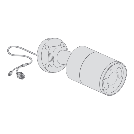
Appearance
1
2
3
4
5
IR LED
1
Microphone
2
Reset
3
Long press the button to reset
the camera to factory settings.
Speaker
4
RJ45 Ethernet Port
5
(supports PoE)
Option 2: Pole Mounting
1. Thread each of the two cable ties through the slits on the back
of the camera's bracket indicated below.
2. Slip the two cable ties through the pole. Tighten them to firmly
attach the pole.
3. Loosen the nut and rotate the camera to the desired position,
then tighten the nut.
Nut
Cable Tie
Install Waterproof Seal for Power Connectors
Install the waterproof seal for the power connectors when the camera is installed
outdoors.
Male Power Connector
Waterproof Seal
6
7
8
Note: Before inserting the microSD
card, unfasten the two fixed screws
to remove the cover.
Grounding Terminal*
at the bottom of the bracket
*The camera comes with a
lightning protection
mechanism. You can ground
9
the camera with ground wire.
Lens
6
White LED
7
microSD Card Slot
8
Insert a microSD card for local storage. Initialize
the SD card via VIGI app or other management
tools before recording videos.
9
Female Power Connector
Advertisement
Table of Contents

Related Manuals for TP-Link VIGI C385 V1


Summary of Contents for TP-Link VIGI C385 V1
- Page 1 • If you are uncertain or uncomfortable performing the *Images may differ from actual products. installation, consult a qualified electrician. ©2023 TP-Link 7106510433 REV1.0.0 Appearance Package Contents Note: Before inserting the microSD card, unfasten the two fixed screws to remove the cover.
- Page 2 • Adapter should be used indoors where the ambient temperature is lower than or equal to 40℃. TP-Link hereby declares that the device is in compliance with the essential requirements and other relevant provisions of directives 2014/30/EU, 2014/35/EU, 2011/65/EU and (EU)2015/863.
Need help?
Do you have a question about the VIGI C385 V1 and is the answer not in the manual?
Questions and answers