
Related Manuals for Supermicro SUPERSERVER 6015C-NT


Summary of Contents for Supermicro SUPERSERVER 6015C-NT
- Page 1 UPER UPER ERVER UPER ERVER UPER ERVER UPER ERVER USER’S MANUAL 6015C-UR 6015C-U 6015C-NTR 6015C-NT ®...
- Page 2 Please Note: For the most up-to-date version of this manual, please see our web site at www.supermicro.com. SUPER MICRO COMPUTER reserves the right to make changes to the product described in this manual at any time and without notice.
-
Page 3: About This Manual
Chapter 2: Server Installation This chapter describes the steps necessary to install the SuperServer 6015C-UR/ 6015C-U/6015C-NTR/6015C-NT into a rack and check out the server confi guration prior to powering up the system. If your server was ordered without processor and memory components, this chapter will refer you to the appropriate sections of the manual for their installation. - Page 4 UPER ERVER 6015C-UR/6015C-U/6015C-NTR/6015C-NT User's Manual Chapter 4: System Safety You should thoroughly familiarize yourself with this chapter for a general overview of safety precautions that should be followed when installing and servicing the SuperServer 6015C-UR/6015C-U/6015C-NTR/6015C-NT. Chapter 5: Advanced Serverboard Setup Chapter 5 provides detailed information on the X7DCU serverboard, including the locations and functions of connections, headers and jumpers.
- Page 5 Preface Notes...
-
Page 6: Table Of Contents
UPER ERVER 6015C-UR/6015C-U/6015C-NTR/6015C-NT User's Manual Table of Contents Chapter 1 Introduction Overview ... 1-1 Serverboard Features ... 1-2 Processors ... 1-2 Memory ... 1-2 UIO ... 1-2 Serial ATA ... 1-2 Onboard Controllers/Ports ... 1-2 Other Features ... 1-3 Server Chassis Features ... 1-3 System Power ... - Page 7 Checking the Serverboard Setup ... 2-8 Checking the Drive Bay Setup ... 2-9 Chapter 3 System Interface Overview ... 3-1 Control Panel Buttons ... 3-1 UID ... 3-1 Reset ... 3-1 Power ... 3-2 Control Panel LEDs ... 3-2 Universal Information LED ... 3-2 NIC2 ...
- Page 8 UPER ERVER 6015C-UR/6015C-U/6015C-NTR/6015C-NT User's Manual 5-12 Installing Software ... 5-24 Supero Doctor III ... 5-25 Chapter 6 Advanced Chassis Setup Static-Sensitive Devices ... 6-1 Precautions ... 6-1 Control Panel ... 6-2 System Fans ... 6-3 System Fan Failure ... 6-3 Drive Bay Installation/Removal ...
-
Page 9: Chapter 1 Introduction
NTR)/SC815TQ-560U (6015C-U/6015C-NT) 1U server chassis and the X7DCU dual processor serverboard. Please refer to our web site for information on operating systems that have been certifi ed for use with the system (www.supermicro.com). In addition to the serverboard and chassis, various hardware components have been... -
Page 10: Serverboard Features
ERVER 6015C-UR/6015C-U/6015C-NTR/6015C-NT User's Manual Serverboard Features At the heart of the SuperServer 6015C-UR/6015C-U/6015C-NTR/6015C-NT lies the X7DCU, a dual processor serverboard based on the Intel 5100 chipset and designed to provide maximum performance. Below are the main features of the X7DCU. (See Figure 1-1 for a block diagram of the chipset). -
Page 11: Other Features
SAS/SATA drives with an optional UIO SAS card. See our web site for details (http://www.supermicro.com/products/nfo/UIO.cfm). 6015C-NTR/6015C-NT: A riser card on the right side of the chassis can support one PCI-E x8 card. The left side supports two PCI-E x8 cards. See section 5-6 for details. -
Page 12: Front Control Panel
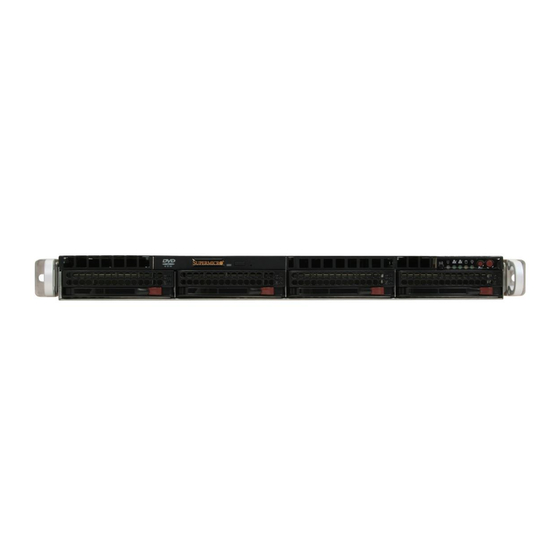
UPER ERVER 6015C-UR/6015C-U/6015C-NTR/6015C-NT User's Manual Front Control Panel The chassis' control panel provides you with system monitoring and control. LEDs indicate system power, HDD activity, network activity (two) and UID/overheat/fan fail/power fail. A main power button and system reset button is also included. -
Page 13: System Block Diagram
Figure 1-1. Intel 5100/ICH9R Chipset: System Block Diagram Note: This is a general block diagram. Please see Chapter 5 for details. Processor#2 1067/1333 PCI-E x8 PCI-E x8 PCI-E x8 RJ45 PCI-E x4 ZOAR RJ45 PCI-E x1 JMB368 DDR 2 16X16M PCI33MHz RN50 CONN... -
Page 14: Contacting Supermicro
UPER ERVER 6015C-UR/6015C-U/6015C-NTR/6015C-NT User's Manual Contacting Supermicro Headquarters Address: Super Micro Computer, Inc. 980 Rock Ave. San Jose, CA 95131 U.S.A. Tel: +1 (408) 503-8000 Fax: +1 (408) 503-8008 Email: marketing@supermicro.com (General Information) support@supermicro.com (Technical Support) Web Site: www.supermicro.com Europe Address: Super Micro Computer B.V. -
Page 15: Chapter 2 Server Installation
You should inspect the box the SuperServer 6015C-UR/6015C-U/6015C-NTR/ 6015C-NT was shipped in and note if it was damaged in any way. If the server itself shows damage you should fi le a damage claim with the carrier who delivered it. -
Page 16: Choosing A Setup Location
UPER ERVER 6015C-UR/6015C-U/6015C-NTR/6015C-NT User's Manual Choosing a Setup Location • Leave enough clearance in front of the rack to enable you to open the front door completely (~25 inches) and approximately 30 inches of clearance in the back of the rack to allow for suffi cient airfl ow and ease in servicing.This product is for installation only in a Restricted Access Location (dedicated equipment rooms, service closets and the like). -
Page 17: Rack Mounting Considerations
• Allow the hot plug SATA drives and power supply modules to cool before touch- ing them. • Always keep the rack's front door and all panels and components on the servers closed when not servicing to maintain proper cooling. Rack Mounting Considerations Ambient Operating Temperature If installed in a closed or multi-unit rack assembly, the ambient operating tempera-... -
Page 18: Installing The System Into A Rack
Installing the System into a Rack This section provides information on installing the 6015C-UR/6015C-U/6015C- NTR/6015C-NT into a rack unit with the rack rails provided. If the system has already been mounted into a rack, you can skip ahead to Sections 2-5 and 2-6. -
Page 19: Installing The Outer Rails
Chapter 2: Server Installation Installing the Outer Rails Begin by measuring the distance from the front rail to the rear rail of the rack. Attach a short bracket to the front side of the right outer rail and a long bracket to the rear side of the right outer rail. -
Page 20: Installing The Server Into The Rack
UPER ERVER 6015C-UR/6015C-U/6015C-NTR/6015C-NT User's Manual Installing the Server into the Rack You should now have rails attached to both the chassis and the rack unit. The next step is to install the server into the rack. Do this by lining up the rear of the chassis rails with the front of the rack rails. -
Page 21: Installing The Server Into A Telco Rack
Chapter 2: Server Installation Installing the Server into a Telco Rack To install the 6015C-UR/6015C-U/6015C-NTR/6015C-NT into a Telco type rack, use two L-shaped brackets on either side of the chassis (four total). First, determine how far follow the server will extend out the front of the rack. Larger chassis should be positioned to balance the weight between front and back. -
Page 22: Checking The Serverboard Setup
UPER ERVER 6015C-UR/6015C-U/6015C-NTR/6015C-NT User's Manual Checking the Serverboard Setup After you install the 6015C-UR/6015C-U/6015C-NTR/6015C-NT in the rack, you will need to open the top cover to make sure the serverboard is properly installed and all the connections have been made. -
Page 23: Checking The Drive Bay Setup
Figure 2-5. Accessing the Inside of the System Checking the Drive Bay Setup Next, you should check to make sure the peripheral drives and the SATA drives and SATA backplane have been properly installed and all connections have been made. Checking the Drives All drives are accessable from the front of the server. - Page 24 UPER ERVER 6015C-UR/6015C-U/6015C-NTR/6015C-NT User's Manual Checking the Airfl ow Airfl ow is provided by four sets of 4-cm fans (each set of fans consists of two fans that are mounted back to back). The system component layout was carefully designed to direct suffi cient cooling airfl ow to the components that generate the most heat.
-
Page 25: Chapter 3 System Interface
System Interface Overview There are several LEDs on the control panel as well as others on the SATA drive carriers to keep you constantly informed of the overall status of the system as well as the activity and health of specifi c components. There are also two buttons on the chassis control panel and an on/off switch on the power supply. -
Page 26: Power
UPER ERVER 6015C-UR/6015C-U/6015C-NTR/6015C-NT User's Manual Power The main power button is used to apply or remove power from the power supply to the server system. Turning off system power with this button removes the main power but keeps standby power supplied to the system. -
Page 27: Nic2
NIC1 Indicates network activity on LAN1 when fl ashing. Indicates IDE channel activity. On the SuperServer 6015C-UR/6015C-U/6015C- NTR/6015C-NT, this light indicates SATA and/or DVD-ROM drive activity when fl ashing. Power Indicates power is being supplied to the system's power supply units. This LED should normally be illuminated when the system is operating. -
Page 28: Hard Drive Carrier Leds
UPER ERVER 6015C-UR/6015C-U/6015C-NTR/6015C-NT User's Manual Hard Drive Carrier LEDs Each hard drive carrier has two LEDs. • Green: When illuminated, the green LED on the front of the drive carrier in- dicates drive activity. A connection to the drive backplane enables this LED to blink on and off when that particular drive is being accessed. -
Page 29: Chapter 4 System Safety
Electrical Safety Precautions Basic electrical safety precautions should be followed to protect yourself from harm and the SuperServer 6015C-UR/6015C-U/6015C-NTR/6015C-NT from damage: • Be aware of the locations of the power on/off switch on the chassis as well as the room's emergency power-off switch, disconnection switch or electrical outlet. -
Page 30: General Safety Precautions
Keep the area around the system clean and free of clutter. • The 6015C-UR/6015C-U/6015C-NTR/6015C-NT weighs approximately 43/41 lbs (19.5/18.6 kg) when fully loaded. When lifting the system, two people at either end should lift slowly with their feet spread out to distribute the weight. -
Page 31: Esd Precautions
• After accessing the inside of the system, close the system back up and secure it to the rack unit after ensuring that all connections have been made. ESD Precautions Electrostatic discharge (ESD) is generated by two objects with different electrical charges coming into contact with each other. -
Page 32: Operating Precautions
Operating Precautions Care must be taken to assure that the chassis cover is in place when the 6015C- UR/6015C-U/6015C-NTR/6015C-NT is operating to assure proper cooling. Out of warranty damage to the system can occur if this practice is not strictly followed. -
Page 33: Chapter 5 Advanced Serverboard Setup
Advanced Serverboard Setup This chapter covers the steps required to install processors and heatsinks to the X7DCU serverboard, connect the data and power cables and install add-on cards. All serverboard jumpers and connections are described and a layout and quick reference chart are included in this chapter. Remember to close the chas- sis completely when you have fi... -
Page 34: Processor And Heatsink Installation
UPER ERVER 6015C-UR/6015C-U/6015C-NTR/6015C-NT User's Manual Processor and Heatsink Installation When handling the processor, avoid placing direct pressure on the label area of the fan. Also, do not place the serverboard on a conductive sur- face, which can damage the BIOS battery and prevent the system from booting up. - Page 35 3. Use your thumb and your index fi nger to hold the CPU at opposite sides. 4. Align pin1 of the CPU (the cor- ner marked with a triangle) with the notched corner of the CPU socket. 5. Find the corner of the CPU that has a semi-circle cutout below a gold dot (CPU key).
- Page 36 UPER ERVER 6015C-UR/6015C-U/6015C-NTR/6015C-NT User's Manual Installing the Heatsink 1. Do not apply any thermal grease to the heatsink or the CPU die; the required amount has already been applied. 2. Place the heatsink on top of the CPU so that the four mounting holes are aligned with those on the (preinstalled) heatsink retention mechanism.
-
Page 37: Connecting Cables
Connecting Cables Now that the processors are installed, the next step is to connect the cables to the serverboard. These include the data (ribbon) cables for the peripherals and control panel and the power cables. Connecting Data Cables The cables used to transfer data from the peripheral devices have been carefully routed in preconfi... -
Page 38: I/O Ports
UPER ERVER 6015C-UR/6015C-U/6015C-NTR/6015C-NT User's Manual other end of the cable to the Control Panel printed circuit board, located just behind the system status LEDs in the chassis. See the Connector Defi nitions section in this chapter for details and pin descrip- tions of JF1. -
Page 39: Installing Memory
Installing Memory Note: Check the Supermicro web site for recommended memory modules. Exercise extreme care when installing or removing DIMM modules to prevent any possible damage. Also note that the memory is inter- leaved to improve performance (see step 1). - Page 40 UPER ERVER 6015C-UR/6015C-U/6015C-NTR/6015C-NT User's Manual Possible System Memory Allocation & Availability System Device Firmware Hub fl ash memory (System BIOS) Local APIC Area Reserved for the chipset I/O APIC (4 Kbytes) PCI Enumeration Area 1 PCI Express (256 MB) PCI Enumeration Area 2...
-
Page 41: Adding Pci Cards
PCI Slot/Card Confi gurations 6015C-UR/6015C-U Left Side Riser Card CSE-R1UU-UE8 (pre-installed) Right Side Riser Card RSC-R1UU-E8R+ (pre-installed) 6015C-NTR/6015C-NT Left Side Riser Card CSE-R1UU-2E8 (pre-installed) Right Side Riser Card RSC-R1UU-E8R+ (pre-installed) Chapter 5: Advanced Serverboard Setup Expansion card supported... -
Page 42: Serverboard Details
UPER ERVER 6015C-UR/6015C-U/6015C-NTR/6015C-NT User's Manual Serverboard Details Figure 5-4. SUPER X7DCU Layout LAN2 JBT1 I-SATA5 I-SATA4 I-SATA3 I-SATA2 JPEW1 I-SATA1 JPEW2 I-SATA0 S I/O Buzzer FAN4 FAN8 JOH1 JCF1 Note: Jumpers not noted are for test purposes only. (not drawn to scale) -
Page 43: X7Dcu Quick Reference
X7DCU Quick Reference Jumper Description JBT1 CMOS Clear JCF1 Compact Flash Master/Slave Select JIDE IDE Enable/Disable JPG1 VGA Enable/Disable JPL1 LAN1/2 Enable/Disable JWD1 Watch Dog Connector Description COM1/COM2 Serial Port/Header FAN 1-8 Chassis/CPU Fan Headers Floppy Floppy Disk Drive Connector IDE Drive Connector I-SATA0 ~ I-SATA5 SATA Ports... -
Page 44: Connector Defi Nitions
UPER ERVER 6015C-UR/6015C-U/6015C-NTR/6015C-NT User's Manual Connector Defi nitions ATX Power Connector The primary ATX power supply con- nector meets the SSI (Superset ATX) 20-pin specifi cation. Make sure that the orientation of the connector is correct. See the table on the right for pin defi... - Page 45 HDD LED The HDD (IDE Hard Disk Drive) LED connection is located on pins 13 and 14 of JF1. Attach the IDE hard drive LED cable to display disk activity. Refer to the table on the right for pin defi nitions. NIC1 LED The NIC1 (Network Interface Control- ler) LED connection is located on pins...
- Page 46 UPER ERVER 6015C-UR/6015C-U/6015C-NTR/6015C-NT User's Manual Power Fail LED The Power Fail LED connection is located on pins 5 and 6 of JF1. Refer to the table on the right for pin defi ni- tions. Reset Button The Reset Button connection is lo- cated on pins 3 and 4 of JF1.
- Page 47 Universal Serial Bus Headers Three additional USB headers (USB2/ USB3 and USB4) are included on the serverboard. These may be used for front side access. A USB cable (not included) is needed for the connec- tion. See the table on the right for pin defi...
- Page 48 UPER ERVER 6015C-UR/6015C-U/6015C-NTR/6015C-NT User's Manual Power LED/Speaker On the JD1 header, pins 1-3 are for a power LED and pins 4-7 are for an external speaker. See the table on the right for speaker pin defi nitions. Note: The speaker connector pins are for use with an external speaker.
- Page 49 Wake-On-LAN The Wake-On-LAN header is desig- nated JWOL1. See the table on the right for pin definitions. You must enable the LAN Wake-Up setting in BIOS to use this feature. You must also have a LAN card with a Wake- on-LAN connector and cable.
- Page 50 UPER ERVER 6015C-UR/6015C-U/6015C-NTR/6015C-NT User's Manual UID Switches There are two Unit Identifi cation (UID) switches on the motherboard. The Front Panel UID Switch connects to pin 13 of JF1. The Rear UID Switch (SW1) is located next to LAN2. Push-...
-
Page 51: Jumper Settings
Jumper Settings Explanation of Jumpers To modify the operation of the serverboard, jumpers can be used to choose between optional settings. Jumpers create shorts between two pins to change the function of the connector. Pin 1 is identifi ed with a square solder pad on the printed cir- cuit board. - Page 52 UPER ERVER 6015C-UR/6015C-U/6015C-NTR/6015C-NT User's Manual LAN Enable/Disable Change the setting of jumper JPL1 to enable or disable the onboard Ether- net (RJ45) ports LAN1 and LAN2. See the table on the right for jumper set- tings. The default setting is enabled.
-
Page 53: 5-10 Onboard Indicators
5-10 Onboard Indicators LAN1/LAN2 LEDs The Ethernet ports (located beside the VGA port) have two LEDs. On each Gigabit LAN port, one LED indicates activity when blinking while the other LED may be green, amber or off to indicate the speed of the connection. See the table on the right for the func- tions associated with the connection speed LED. -
Page 54: 5-11 Floppy, Ide And Sata Drive Connections
UPER ERVER 6015C-UR/6015C-U/6015C-NTR/6015C-NT User's Manual 5-11 Floppy, IDE and SATA Drive Connections Note the following when connecting the fl oppy and hard disk drive cables: • The fl oppy disk drive cable has seven twisted wires. • A red mark on a wire typically designates the location of pin 1. - Page 55 IDE Connector There are no jumpers to con- fi gure the onboard IDE connec- tor. See the table on the right for pin defi nitions. SATA Ports See the table on the right for pin defi nitions for the onboard SATA ports.
-
Page 56: 5-12 Installing Software
5-12 Installing Software After the hardware has been installed, you should fi rst install the operating system and then the drivers. The necessary drivers are all included on the Supermicro CDs that came packaged with your motherboard. Driver/Tool Installation Display Screen Note: Click the icons showing a hand writing on paper to view the readme fi... -
Page 57: Supero Doctor Iii
Chapter 5: Advanced Serverboard Setup Supero Doctor III The Supero Doctor III program is a Web base management tool that supports remote management capability. It includes Remote and Local Management tools. The local management is called SD III Client. The Supero Doctor III program included on the CDROM that came with your motherboard allows you to monitor the environment and operations of your system. - Page 58 Supero Doctor III Interface Display Screen (Remote Control) Note: SD III Software Revision 1.0 can be downloaded from our Web Site at: ftp:// ftp.supermicro.com/utility/Supero_Doctor_III/. You can also download SDIII User's Guide at: http://www.supermicro.com/PRODUCT/Manuals/SDIII/UserGuide.pdf. For Linux, we will still recommend Supero Doctor II.
-
Page 59: Chapter 6 Advanced Chassis Setup
Advanced Chassis Setup This chapter covers the steps required to install components and perform mainte- nance on the SC815TQ-R650U/SC815TQ-560U chassis. For component installa- tion, follow the steps in the order given to eliminate the most common problems encountered. If some steps are unnecessary, skip ahead to the next step. Tools Required: The only tool you will need to install components and perform maintenance is a Philips screwdriver. -
Page 60: Control Panel
Power Supply Module USB Ports Mouse/Keyboard COM1 Port Note: the SC815TQ-560U chassis (6015C-U/6015C-NT) has only a single power supply mod- ule. Control Panel The control panel (located on the front of the chassis) must be connected to the JF1 connector on the serverboard to provide you with system status indications. These wires have been bundled together as a ribbon cable to simplify the connection. -
Page 61: System Fans
System Fans Four 4-cm heavy duty counter-rotating fans provide the cooling for the SuperServer 6015C-UR/6015C-U/6015C-NTR/6015C-NT. Each fan unit is actually made up of two fans joined back-to-back, which rotate in opposite directions. This counter-rotat- ing action generates exceptional airfl ow and works to dampen vibration levels. It is... -
Page 62: Drive Bay Installation/Removal
UPER ERVER 6015C-UR/6015C-U/6015C-NTR/6015C-NT User's Manual Figure 6-2. System Cooling Fans Drive Bay Installation/Removal Removing the Front Bezel If your system has a front bezel (optional) attached to the chassis, you must fi rst remove it to gain access to the drive bays. To remove the bezel, fi rst unlock the front of the chassis then press the release knob (see Figure 6-3). -
Page 63: Accessing The Drive Bays
DVD-ROM/Floppy Disk Drives: For installing/removing a DVD-ROM or fl oppy disk drive, you will need to gain access to the inside of the 6015C-UR/6015C-U/6015C- NTR/6015C-NT by removing the top cover of the chassis. Proceed to the "DVD- ROM and Floppy Drive Installation" section later in this chapter for instructions. -
Page 64: Sata Drive Installation
UPER ERVER 6015C-UR/6015C-U/6015C-NTR/6015C-NT User's Manual SATA Drive Installation The SATA drives are mounted in drive carriers to simplify their installation and removal from the chassis. These carriers also help promote proper airfl ow for the drive bays. For this reason, even empty carriers without drives installed must remain in the chassis. - Page 65 Installing/Removing a SATA Drive To remove a carrier, push the release button located beside the drive LEDs. Swing the colored handle fully out and use it to pull the unit straight out (see Figure 6-5). Note: Your operating system must have RAID support to enable the hot-plug ca- pability of the SATA drives.
-
Page 66: Dvd-Rom And Floppy Drive Installation
DVD-ROM and Floppy Drive Installation The top cover of the chassis must be opened to gain full access to the DVD-ROM and fl oppy drive bays. The 6015C-UR/6015C-U/6015C-NTR/6015C-NT accomo- dates only slim-line DVD-ROM drives. Side mounting brackets are needed to mount a slim-line DVD-ROM drive in the 6015C-UR/6015C-U/6015C-NTR/6015C-NT server. -
Page 67: Power Supply
Information LED on the control panel will blink slowly and remain so until the failed module has been replaced. Replacement modules can be ordered directly from Supermicro (see contact information in the Preface). The power supply modules have a hot-swap capability, meaning you can replace the failed module without powering down the system. -
Page 68: 6015C-U/6015C-Nt
Finish by plugging the AC power cord back into the module. 6015C-U/6015C-NT The SuperServer 6015C-U/6015C-NT has a single 560 watt power supply, which is auto-switching capable. This enables it to automatically sense and operate with a 100v - 240v input voltage. - Page 69 Chapter 6: Advanced Chassis Setup Figure 6-6. Removing/Replacing the Power Supply 6-11...
- Page 70 UPER ERVER 6015C-UR/6015C-U/6015C-NTR/6015C-NT User's Manual Notes 6-12...
-
Page 71: Chapter 7 Bios
Please refer to the Manual Download area of the Super Micro web site <http://www.supermicro.com> for any changes to the BIOS that may not be refl ected in this manual. -
Page 72: Running Setup
UPER ERVER 6015C-UR/6015C-U/6015C-NTR/6015C-NT User's Manual Running Setup Default settings are in bold text unless otherwise noted. The BIOS setup options described in this section are selected by choosing the ap- propriate text from the main BIOS Setup screen. All displayed text is described in this section, although the screen display is often all you need to understand how to set the options (see the next page). -
Page 73: Main Bios Setup Menu
Main BIOS Setup Menu Main Setup Features System Time To set the system date and time, key in the correct information in the appropriate fi elds. Then press the <Enter> key to save the data. System Date Using the arrow keys, highlight the month, day and year fi elds, and enter the correct data. - Page 74 UPER ERVER 6015C-UR/6015C-U/6015C-NTR/6015C-NT User's Manual SATA Port1, SATA Port2, SATA Port3, SATA Port4, SATA Port5 and SATA Port6 These settings allow the user to set the parameters of SATA Port, SATA Port, SATA Port3 and SATA Port4. Hit <Enter> to activate the following sub-menu screen for detailed options of these items.
- Page 75 Chapter 7: BIOS 32 Bit I/O This option allows the user to enable or disable the function of 32-bit data transfer. The options are Enabled and Disabled. Transfer Mode This option allows the user to set the transfer mode. The options are Standard, Fast PIO1, Fast PIO2, Fast PIO3, Fast PIO4, FPIO3/DMA1 and FPIO4/DMA2.
-
Page 76: Advanced Setup
UPER ERVER 6015C-UR/6015C-U/6015C-NTR/6015C-NT User's Manual SATA AHCI Enable Select Enable to enable the Serial ATA Advanced Host Interface. (Use caution when enabling. This feature is for advanced programmers only. The options are Enabled and Disabled.) System Memory This display informs you how much system memory is recognized as being present in the system. - Page 77 Chapter 7: BIOS Power Button Behavior If set to Instant-Off, the system will power off immediately as soon as the user hits the power button. If set to 4-sec., the system will power off when the user presses the power button for 4 seconds or longer. The options are Instant-Off and 4-sec override.
- Page 78 UPER ERVER 6015C-UR/6015C-U/6015C-NTR/6015C-NT User's Manual Memory Cache Cache System BIOS Area This setting allows you to designate a reserve area in the system memory to be used as a System BIOS buffer into which BIOS can write (cache) data. Select Write Protect to enable this function, and this area will be reserved for BIOS ROM ac- cess only.
- Page 79 Cache Extended Memory Area If enabled, this feature will allow the data stored in the extended memory area to be cached (written) into a buffer, a storage area in the Static DROM (SDROM) or written into the L1/L2/L3 cache inside the CPU to speed up CPU operations. Select Uncached to disable this function.
-
Page 80: Advanced Chipset Control
UPER ERVER 6015C-UR/6015C-U/6015C-NTR/6015C-NT User's Manual Latency Timer This setting allows you to set the clock rate for the Bus Master. A high-priority, high-throughout device may benefi t from a greater clock rate. The options are Default, 0020h, 0040h, 0060h, 0080h, 00A0h, 00C0h, 00E0h and Other. For Unix, Novell and other Operating Systems, please select "Other". - Page 81 Chapter 7: BIOS Channel 0 Rank Sparing/Channel 1 Rank Sparing Select Enable to enable the function of memory sparing for Memory Bus Branch 0 or Branch 1. The options are Enabled and Disabled. Enhanced x8 Detection Select Enabled to enable Enhanced x8 DRAM UC Error Detection. The options are Disabled and Enabled.
- Page 82 UPER ERVER 6015C-UR/6015C-U/6015C-NTR/6015C-NT User's Manual Advanced Processor Options Access the submenu to make changes to the following settings. CPU Speed This is a display that indicates the speed of the installed processor. Frequency Ratio (Available if supported by the CPU) The feature allows the user to set the internal frequency multiplier for the CPU.
- Page 83 Chapter 7: BIOS Adjacent Cache Line Prefetch (Available when supported by the CPU) The CPU fetches the cache line for 64 bytes if this option is set to Disabled. The CPU fetches both cache lines for 128 bytes as comprised if Enabled. The options are Disabled and Enabled.
- Page 84 UPER ERVER 6015C-UR/6015C-U/6015C-NTR/6015C-NT User's Manual I/O Device Confi guration Access the submenu to make changes to the following settings. KBC Clock Input This setting allows you to select clock frequency for KBC. The options are 6MHz, 8MHz, 12MHz and 16MHz.
-
Page 85: Dmi Event Logging
Chapter 7: BIOS Base I/O Address This setting allows you to select the base I/O address for the Floppy port. The op- tions are Primary and Secondary. DMI Event Logging Access the submenu to make changes to the following settings. Event Log Validity This is a display to inform you of the event log validity. -
Page 86: Hardware Monitor Logic
UPER ERVER 6015C-UR/6015C-U/6015C-NTR/6015C-NT User's Manual Console Type This item allows you to choose the console redirection type. The options are VT100, VT100/8bit, PC-ANSI/7bit, PC ANSI, VT100+ and VT-UTF8. Flow Control This item allows you to set the fl ow control for the console redirection. The options are None, XON/XOFF and CTS/RTS. - Page 87 Chapter 7: BIOS Voltage Monitoring The following items will be monitored and displayed: Vcore A, Vcore B, -12V, P1V5, +3.3V, +12V, 5Vsb, 5VDD, P_VTT, Vbat. Note: In the Windows OS environment, the Supero Doctor III settings take prece- dence over the BIOS settings. When fi rst installed, Supero Doctor III adopts the temperature threshold settings previously set in the BIOS.
- Page 88 UPER ERVER 6015C-UR/6015C-U/6015C-NTR/6015C-NT User's Manual IPMI (The option is available only when an IPMI card is installed in the system.) IPMI Specifi cation Version This item displays the current IPMI Version. BMC HW/Firmware Version This item displays the current Firmware Version.
- Page 89 BIOS POST Errors Enabling this function to log POST errors. The options are Enabled and Dis- abled. BIOS POST Watch Dog Set to Enabled to enable POST Watch Dog. The options are Enabled and Dis- abled. OS Boot Watch Dog Set to Enabled to enable OS Boot Watch Dog.
-
Page 90: Security
UPER ERVER 6015C-UR/6015C-U/6015C-NTR/6015C-NT User's Manual Realtime Sensor Data This feature display information from motherboard sensors, such as temperatures, fan speeds and voltages of various components. Security Choose Security from the Phoenix BIOS Setup Utility main menu with the arrow keys. You should see the following display. Security setting options are displayed by highlighting the setting using the arrow keys and pressing <Enter>. - Page 91 Chapter 7: BIOS Supervisor Password Is: This indicates if a supervisor password has been entered for the system. Clear means such a password has not been used and Set means a supervisor password has been entered for the system. User Password Is: This indicates if a user password has been entered for the system.
-
Page 92: Boot
UPER ERVER 6015C-UR/6015C-U/6015C-NTR/6015C-NT User's Manual Password on Boot This setting allows you to determine if a password is required for a user to enter the system at bootup. The options are Enabled (password required) and Disabled (password not required). Boot Choose Boot from the Phoenix BIOS Setup Utility main menu with the arrow keys. -
Page 93: Exit
Chapter 7: BIOS Exit Choose Exit from the Phoenix BIOS Setup Utility main menu with the arrow keys. You should see the following display. All Exit BIOS settings are described in this section. Exit Saving Changes Highlight this item and hit <Enter> to save any changes you made and to exit the BIOS Setup utility. - Page 94 UPER ERVER 6015C-UR/6015C-U/6015C-NTR/6015C-NT User's Manual Save Changes Highlight this item and hit <Enter> to save any changes you made. You will remain in the Setup utility. 7-24...
-
Page 95: Appendix A Bios Post Messages
Appendix A: BIOS POST Messages Appendix A BIOS POST Messages During the Power-On Self-Test (POST), the BIOS will check for problems. If a prob- lem is found, the BIOS will activate an alarm or display a message. The following is a list of such BIOS messages. Failure Fixed Disk Fixed disk is not working or not confi... - Page 96 UPER ERVER 6015C-UR/6015C-U/6015C-NTR/6015C-NT User's Manual System CMOS checksum bad - Default confi guration used System CMOS has been corrupted or modifi ed incorrectly, perhaps by an application program that changes data stored in CMOS. The BIOS installed Default Setup Values.
- Page 97 Appendix A: BIOS POST Messages CPU ID: CPU socket number for Multi-Processor error. EISA CMOS not writeable ServerBIOS2 test error: Cannot write to EISA CMOS. DMA Test Failed ServerBIOS2 test error: Cannot write to extended DMA (Direct Memory Access) registers. Software NMI Failed ServerBIOS2 test error: Cannot generate software NMI (Non-Maskable Interrupt).
- Page 98 UPER ERVER 6015C-UR/6015C-U/6015C-NTR/6015C-NT User's Manual I/O device IRQ confl ict I/O device IRQ confl ict error. PS/2 Mouse Boot Summary Screen: PS/2 Mouse installed. nnnn kB Extended RAM Passed Where nnnn is the amount of RAM in kilobytes successfully tested.
- Page 99 Appendix A: BIOS POST Messages Press <F2> to enter Setup Optional message displayed during POST. Can be turned off in Setup. PS/2 Mouse: PS/2 mouse identifi ed. Run the I2O Confi guration Utility One or more unclaimed block storage devices have the Confi guration Request bit set in the LCT.
- Page 100 UPER ERVER 6015C-UR/6015C-U/6015C-NTR/6015C-NT User's Manual Notes...
-
Page 101: Appendix B Bios Post Codes
Appendix B BIOS POST Codes This section lists the POST (Power On Self Test) codes for the PhoenixBIOS. POST codes are divided into two categories: recoverable and terminal. Recoverable POST Errors When a recoverable type of error occurs during POST, the BIOS will display an POST code that describes the problem. - Page 102 UPER ERVER 6015C-UR/6015C-U/6015C-NTR/6015C-NT User's Manual POST Code Description 1-2-2-3 BIOS ROM checksum Initialize cache before memory Auto size 8254 timer initialization 8237 DMA controller initialization Reset Programmable Interrupt Controller 1-3-1-1 Test DRAM refresh 1-3-1-3 Test 8742 Keyboard Controller Set ES segment register to 4 GB...
- Page 103 POST Code Description Test RAM between 512 and 640 kB Test extended memory Test extended memory address lines Jump to UserPatch1 Confi gure advanced cache registers Initialize Multi Processor APIC Enable external and CPU caches Setup System Management Mode (SMM) area Display external L2 cache size Load custom defaults (optional) Display shadow-area message...
- Page 104 UPER ERVER 6015C-UR/6015C-U/6015C-NTR/6015C-NT User's Manual POST Code Description Set up Power Management Initialize security engine (optional) Enable hardware interrupts Determine number of ATA and SCSI drives Set time of day Check key lock Initialize typematic rate Erase <ESC> prompt Scan for <ESC> key stroke Enter SETUP Clear Boot fl...
- Page 105 The following are for boot block in Flash ROM POST Code Description Initialize the chipset Initialize the bridge Initialize the CPU Initialize system timer Initialize system I/O Check force recovery boot Checksum BIOS ROM Go to BIOS Set Huge Segment Initialize Multi Processor Initialize OEM special code Initialize PIC and DMA...
- Page 106 UPER ERVER 6015C-UR/6015C-U/6015C-NTR/6015C-NT User's Manual Notes...
-
Page 107: Appendix C System Specifi Cations
Intel ICH9R on-chip controller for six-port Serial ATA (RAID 0, 1 5 and 10 supported) Drive Bays 6015C-NTR/6015C-NT: Four (4) hot-swap drive bays to house four (4) SATA drives 6015C-UR/6015C-U: Four (4) hot-swap drive bays to house four (4) SAS/SATA drives (with... - Page 108 Dimensions: (WxHxD) 17 x 1.7 x 25.6 in. (432 x 43 x 650 mm) Weight 6015C-UR/6015C-NTR: Gross (Bare Bone): 43 lbs. (19.5 kg.) 6015C-U/6015C-NT: Gross (Bare Bone): 41 lbs. (18.6 kg.) System Cooling Four (4) 4-cm heavy-duty counter-rotating fans System Input Requirements...
- Page 109 Appendix C: System Specifi cations Operating Environment Operating Temperature: 10º to 35º C (50º to 95º F) Non-operating Temperature: -40º to 70º C (-40º to 158º F) Operating Relative Humidity: 8% to 90% (non-condensing) Non-operating Relative Humidity: 5 to 95% (non-condensing) Regulatory Compliance Electromagnetic Emissions: FCC Class A, EN 55022 Class A, EN 61000-3-2/-3-3, CISPR 22 Class A...
- Page 110 UPER ERVER 6015C-UR/6015C-U/6015C-NTR/6015C-NT User's Manual Notes...
Need help?
Do you have a question about the SUPERSERVER 6015C-NT and is the answer not in the manual?
Questions and answers