Table of Contents
Advertisement
Quick Links
TM
INSTALLATION MANUAL
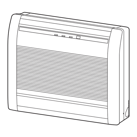
INDOOR UNIT (Floor type)
For authorized service personnel only.
INSTALLATIONSANLEITUNG
INNENGERÄT (Fußbodentyp)
Nur für autorisiertes Fachpersonal.
MANUEL D'INSTALLATION
UNITÉ INTÉRIEURE (Type sol)
Pour le personnel agréé uniquement.
EEV internal model
MANUAL DE INSTALACIÓN
AG*A004GCEH
AG*A007GCEH
UNIDAD INTERIOR (Tipo suelo)
AG*A009GCEH
Únicamente para personal de servicio autorizado.
AG*A012GCEH
MANUALE DI INSTALLAZIONE
AG*A014GCEH
UNITÀ INTERNA (Tipo da pavimento)
EEV external model
A uso esclusivo del personale tecnico autorizzato.
AG*E004GCEH
ΕΓΧΕΙΡΙΔΙΟ ΕΓΚΑΤΑΣΤΑΣΗΣ
AG*E007GCEH
AG*E009GCEH
ΕΣΩΤΕΡΙΚΗ ΜΟΝΑΔΑ (Τύπος δαπέδου)
AG*E012GCEH
Μόνο για εξουσιοδοτημένο τεχνικό προσωπικό.
AG*E014GCEH
MANUAL DE INSTALAÇÃO
UNIDADE INTERIOR (Tipo de chão)
Apenas para técnicos autorizados.
РУКОВОДСТВО ПО УСТАНОВКЕ
ВНУТРЕННИЙ МОДУЛЬ (Напольный тип)
Только для авторизованного обслуживающего персонала.
MONTAJ KILAVUZU
İÇ ÜNİTE (Yer tipi)
Yalnızca yetkili servis personeli için.
MADE IN P.R.C.
Refer to the rating label for the serial number,
[Original instructions]
manufactured year and month.
PART No. 9382568047
Advertisement
Table of Contents

Related Manuals for Fujitsu AirStage AG A004GCEH Series


Summary of Contents for Fujitsu AirStage AG A004GCEH Series
- Page 1 INSTALLATION MANUAL INDOOR UNIT (Floor type) For authorized service personnel only. INSTALLATIONSANLEITUNG INNENGERÄT (Fußbodentyp) Nur für autorisiertes Fachpersonal. MANUEL D’INSTALLATION UNITÉ INTÉRIEURE (Type sol) Pour le personnel agréé uniquement. EEV internal model MANUAL DE INSTALACIÓN AG*A004GCEH AG*A007GCEH UNIDAD INTERIOR (Tipo suelo) AG*A009GCEH Únicamente para personal de servicio autorizado.
-
Page 2: Table Of Contents
INSTALLATION MANUAL This mark indicates procedures which, if improperly performed, PART No. 9382568047 CAUTION might possibly result in personal harm to the user, or damage VRF system indoor unit (Floor type) to property. Read carefully all security information before use or install the air conditioner. Do not attempt to install the air conditioner or a part of the air conditioner by yourself. -
Page 3: Accessories
2.3. Accessories 3. INSTALLATION WORK Correct initial installation location is important because it is difficult to move unit after it is WARNING installed. For installation purposes, be sure to use the parts supplied by the manufacturer or other 3.1. Selecting an installation location prescribed parts. -
Page 4: Installation Dimension
3.2. Installation dimension 3.4. Side panel L, R removal and installation (Unit: mm) 100 or more The intake grille removal (1) Open the intake grille. (2) Remove the rope. 80 or more (3) Lay down the intake grille, until the axle at the bottom of the intake grille is removed. The intake grille installation (1) The fixing axle of the intake grille is installed on the Panel. -
Page 5: Indoor Unit Installation
For RIGHT REAR or LEFT REAR piping 3.7. Installing the wall hook bracket (The following figure is a front view of the indoor unit installation location.) (1) Install the wall hook bracket so that it is correctly positioned horizontally and vertical- Unit: mm ly. -
Page 6: Flare Connection (Pipe Connection)
Rear piping Left piping 4.3. Flare connection (pipe connection) Back wall WARNING Tighten the flare nuts with a torque wrench using the specified tightening method. Oth- erwise, the flare nuts could break after a prolonged period, causing refrigerant to leak and generate hazardous gas if the refrigerant comes into contact with a flame. -
Page 7: Electrical Wiring
A. Current breaker requirements 5. ELECTRICAL WIRING Model • MCA: Minimum Circuit Ampacity • MFA: Maximum Fuse Ampacity AG*A004GCEH 0.16 A WARNING When the power crossover wiring is done, make AG*A007GCEH 0.17 A it so that the total of the MCA of the connected Electrical work must be performed in accordance with this Manual by a person certified RB units and indoor units does not exceed the AG*A009GCEH... -
Page 8: Unit Wiring
5.3.2 Transmission and Remote controller cable 5.3. Unit wiring Transmission cable Remote controller cable • Before attaching the cable to terminal block. 30 mm 30 mm 5.3.1 Power supply cable Shield 25 mm cable (no film) 40 mm Earth • Connect remote controller and transmission cables as shown in figure below. 35 mm (ground) cable PROHIBITED... -
Page 9: Optional Parts Wiring
5.4.3 EV kit cable connecting (EEV external model only) Name Application Power indicator lamp (green) Indicates the state of the power supply. Refer to “Power Earth (ground) wire of EV kit cable indicator lamp status” following. EV kit cable CNA01 Apply voltage terminal For external input CNA03... -
Page 10: External Input And External Output (Optional Parts)
When connected to Dry contact terminals of multiple indoor units with a connected unit, 5.6. External input and external output (Optional parts) insulate each indoor unit with relay, etc. as shown on below example. 5.6.1 External input P.C.B • Indoor unit can be Operation/Stop, Emergency stop or Forced stop by using indoor unit PCB CNA01 or CNA02. -
Page 11: Finishing
● Forced thermostat off function Cloth Wrap the pipes Insulation of indoor [“Edge” input only] tape with cloth tape unit pipes Function Connector Input signal Command setting There are no OFF → ON Thermostat off Ch3 of CNA03 or 60-00 gaps CNA04 ON →... -
Page 12: Custom Code Setting
7.1.1 Indoor unit address 7.3. Function setting • Rotary switch (IU AD × 1)..Factory setting “0” • Rotary switch (IU AD × 10)..Factory setting “0” WARNING When connecting multiple indoor units to 1 refrigerant system, set the address at IU AD SW as shown in the Table A Please make this setting after completing all construction works. -
Page 13: Test Run
• Setting details Function Function Setting number Default Details number Function number Item Setting number Forced Indoor unit address 00 to 63 thermostat Refrigeration address 00 to 99 For use with a remote controller, set all rotary switches to 0, and refer to “7.1. Setting the address”... -
Page 14: Error Codes
10. ERROR CODES If you use a wired type remote controller, error codes will appear on the remote controller display. If you use a wireless remote controller, the lamp on the photodetector unit will output error codes by way of blinking patterns. See the lamp blinking patterns and error codes in the table below.
Need help?
Do you have a question about the AirStage AG A004GCEH Series and is the answer not in the manual?
Questions and answers