
Related Manuals for Daitsu CSAD KIAWP 250


Summary of Contents for Daitsu CSAD KIAWP 250
- Page 1 USER MANUAL CHILLER INVERTER R-32 Serie CSAD KIAWP 250 CSAD KIAWP 300 CSAD KIAWP 450 Édition 03/2023...
- Page 2 ● This manual gives detailed description of the precautions that should be brought to your attention during operation. ● In order to ensure correct service of the wire controller please read this manual carefully before using the unit. ● For convenience of future reference, keep this manual after reading...
- Page 3 Restore initialization If the user accidentally sets the display language of the wire controller to a language that the user does not know, the following three steps can be used to restore the wire controller to the factory setting and reset the display language: 1)Power off the wireline controller and power it on again.
-
Page 4: Table Of Contents
Contents 1 Safety Precautions ................1 2 Overview of Wired Controller ............3 3 Function Introduction................8 4 Attached Table 1:Outdoor unit errors and protection codes..38 5 Attached Table About Modbus ............42... -
Page 5: Safety Precautions
1 Safety Precautions The product and Operation and Installation Instructions record the following content, including the operation method, how to prevent harms to others and property losses, and how to use the product correctly and safely. Read the text after understanding the content (identification and marker maps) below carefully, and observe the precautions below. - Page 6 1 Safety Precautions Icon Name It indicates "prohibited". The specific content of prohibition is provided using graphics or text in the icon or nearby. It indicates "mandatory". The specific mandatory content is provided using graphics or text in the icon or nearby. Entrust your distributor or a professional to install the product.
-
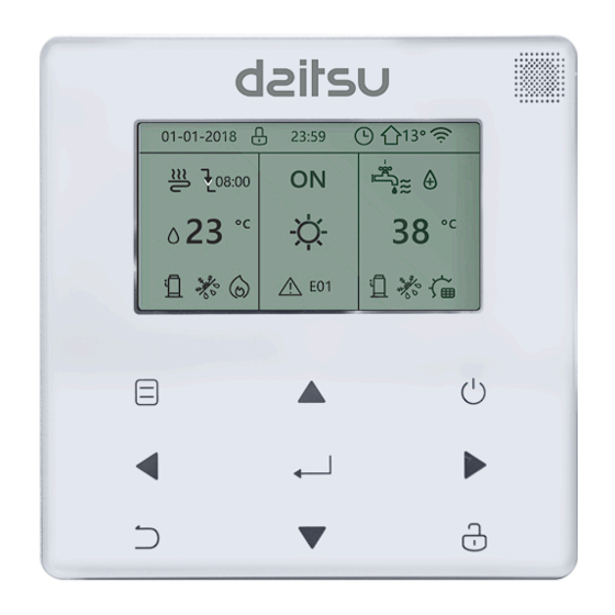
Page 7: Overview Of Wired Controller
2 Overview of Wired Controller Basic using conditions: 1)Power range: power input: AC 8V ~ 12V; 2)Operating temperature: -20℃~60℃; Operating humidity: RH40%~RH90%; Where: HP—HEAT PUMP;CO—ONLY COOLING;FC—FREE COOLING. It’s a general manual. The functions of different models are different. The wired controller automatically recognizes and hides irrelevant interfaces. - Page 8 2 Overview of Wired Controller HP:No icon Heating mode 12/04/2019 MON 10:35A Cooling mode 40 C DHW mode Set temperature COOL(FC:COMP/MIX/FC) HEAT /HEAT/ ONLINE 16 Number of parallel units DHW(DISPLAY ONLY IN SINGLE PUMP) Current ERROR ERRORE 1 Units operating Silent Compressor mode on...
-
Page 9: Function Introduction
3 Function Introduction Power on for the first time or restore factory settings, you need to preset: SETTING ADDRESS and GENERAL SETTING. Click “ ” after setting. Please follow the interface prompts. 3.1 Unlocking/Locking Operation When the wired controller is locked, press and hold the " "... - Page 10 LOCK UNLOCK: ON UNLOCK: OFF 12/04/2019 MON 10:35A 12/04/2019 MON 10:35A 12/04/2019 MON 10:35A HP-COOLING COOL COOL COOL ONLINE 16 ONLINE 16 ONLINE 16 12/04/2019 MON 10:35A MON 10:35A MON 10:35A 12/04/2019 12/04/2019 CO-COOLING COOL COOL COOL ONLINE 16 ONLINE 16 ONLINE 16 12/04/2019 MON 10:35A...
- Page 11 3.3 Mode Setting In Unlock mode, Press " " button to enter the menu setting interface, Press "▼" and "▲" buttons to select "MODE" and set a mode, and Press " " button as shown in the above figure to access the submenu (mode setting).
- Page 12 3.4 Menu Setting When the wired controller is unlocked, press “ ” to enter menu setting page as follows: MODE (DISABLE) MODE USER MENU USER MENU SERVICE MENU SERVICE MENU PROJECT MENU PROJECT MENU The default selection is “MODE” and choose the menu you need by pressing "▲▼" . Press “...
- Page 13 Users choose functions by "▲▼". Select "QUERY" in the "USER MENU" interface to access the query function. The interface display and operation are as follows: QUERY STATE QUERY TEMP QUERY HISTORY ERRORS QUERY State query Select “STATE QUERY” and press“ ”.
- Page 14 Temp query Select “TEMP QUERY” and press“ ”. Display as follows: TEMP QUERY # SELECT ADDESS ℃ INLET WATER TEMP ℃ OUTLET WATER TEMP TOTAL OUTWATER ℃ TEMP ℃ AMBIENT TEMP BACK Select address by pressing “ ◄”, “ ►” to view the temperature of the unit at that address. Back to upper menu by “...
- Page 15 Timer setting Select “TIMER” and press“ ”. Display as follows: TIMER TIMER DAILY TIMER DAILY TIMER(DISABLE) WEEKLY SCHEDULE WEEKLY SCHEDULE(DISABLE) Note: After MODBUS control and the remote control of the external machine are used, the daily and weekly time settings of the wired controller are invalid, and users cannot enter the timing menu for setting.
- Page 16 Only one setting is enabled between "DAILY TIMER" and "WEEKLY SCHEDULE". If any of the pattern in "WEEKLY SCHEDULE" is set to ON, "DAILY TIMER" is disabled. "DAILY TIMER" can be set across days, but "WEEKLY SCHEDULE" can’t. Users can set up to two timers, and set the ON or OFF time (set the interval of time to 10 minutes) 、 operation mode(there are heating, cooling and DHW modes for single pump;...
- Page 17 the homepage. When two timers overlap, the second setting takes precedence. Weekly schedule setting: Select “WEEKLY SCHEDULE” and press“ ”. Display as follows: WEEKLY SCHEDULE MONDAY TIMER MONDAY TIMER WEEKLY SCHEDULE TIMER ℃ WEEKLY SWITCH SILENT MODE NIGHT TIME ON 10:00 SILENT1 TIME OFF...
- Page 18 Press "▲" and "▼" to select the date, time, and time format to be set. Adjust their parameters by “ ◄ ” or “ ►”, and press “ ” to save. The backlight time setting range is 10-1200s, the default is 60s, and each adjustment is 10s. Back to previous page by “...
- Page 19 Press "▲" and "▼" to select “YES” or “NO” and press “ ” to confirm. "YES" means the function is valid, "NO" means invalid. Note:Some models do not have this function. Please refer to the instructions of the outdoor machine for whether they have anti-snow control function. Silent mode: Select “SILENT SWITCH”...
- Page 20 DWH SWITCH # SELECT ADDESS DWH SWITCH DHW FIRST Press "▲" and "▼" to switch between SELECT ADDRESS, DHW SWITCH and DHW FIRST. Then press“ ◄ ” or “ ►” to adjust parameters. Only when DHW SWITCH selects YES, the following can be set. Note:DHW SWITCH is only available for custom made DHW models.
- Page 21 SERVICE MENU PLEASE INPUT THE PASSWORD 0 0 0 Press "▲" and "▼" buttons to change the number to enter, and Press "◄" and "►" buttons to change the bit code to enter. After the number is entered, the display is not changed. After entering the password, Press "...
- Page 22 State query Press "▲" or "▼" to select “STATE QUERY” under “SERVICE MENU” page. Then press “ ” to enter submenu. STATE QUERY STATE QUERY STATE QUERY 3.83 SELECT ADDRESS H-P PRESSURE TZ TEMP -20℃ ODU MODEL L-P PRESSURE 1.00 MPa T3 TEMP -20℃...
- Page 23 Clear history errors: Press "▲" or "▼" to select “CLEAR HISTORY ERRORS” and confirm by “ ”. SERVICE MENU CLEAR HISTORY ERRORS STATE QUERY CLEAR UNIT HISTORY ERRORS CLEAR HISTORY ERROR CLEAR ALL HISTORY ERRORS SETTING ADDRESS CLEAR LOCK ERROR HEAT CONTROL CLEAR RUN TIME Press "▲"...
- Page 24 Press"▲" or "▼" to select “ ” and press “ ” to confirm. Display as follows: CLEAR LOCK ERROR CLEAR LOCK ERR DO YOU WANT TO CLEAR? press “ ◄” or “ ►” to select YES or NO, and press “ ”...
- Page 25 Press"▲" or "▼" to select “ ” and press “ ” to confirm. Display as follows: CLEAR RUN TIME CLEAR RUN TIME SELECT ADDRESS CLEAR COMP TIME? CLEAR FIX PUMP TIME? CLEAR INV PUMP TIME? Press "▲" or "▼" to select “SELECT ADDRESS”, press “ ◄” or “ ►” to select address value. Press "▲"...
- Page 26 SERVICE MENU HEAT CONTROL STATE QUERY HEAT1 CLEAR HISTORY ERROR HEAT2 SETTING ADDRESS FORCED HEAT2 OPEN HEAT CONTROL Press "▲" or "▼" to select item to be set. Press “ ” and enter submenu. HEAT1 HEAT2 HEAT1 ENABLE ALL HEAT2 DISABLE TEMP- SELECT ADDRESS ℃...
- Page 27 Temperature Compensation: Press "▲" or "▼" to select “TEMPERATURE COMPENSATION” under “SERVICE MENU” page. Press “ ” and enter submenu. TEMP COMPENSATION TEMP COMPENSATION SERVICE MENU COOL MODE ENABLE ℃ HEAT MODE ENABLE ℃ TMEPERATURE COMPENSATION T4 COOL-1 T4 HEAT-1 ℃...
- Page 28 Under “FORCED PUMP OPEN” page, press "▲" or "▼" to select item and press “ ◄ ” or “ ► ” to set value. Press “ ” to confirm or “ ” to back. If the unit at that address is ON, the pump cannot be controlled by the wired controlled.
- Page 29 Manual Defrost Press "▲" or "▼" to select “MANUAL DEFROST” under “SERVICE MENU” page. Press “ ” and enter submenu. MANUAL DEFROST SERVICE MENU SELECT ADDRESS TMEPERATURE COMPENSATION MANUAL DEFRIOST PUMP CONTROL MANUAL DEFROST LOW OUTLET WATER CONTROL Press "▲" or "▼" to select item to be set and press “ ◄ ” or “ ► ” to set value. Press “ ”...
- Page 30 LOW OUTLET WATRER CONTROL The setting temp is below 5 degrees. please confirm whether it is an antifreeze system? Note:Only applicable to MC-SU **-RN8L-B series models.For other models, please refer to the instructions of the outdoor machine. Vacuum mode Press "▲" or "▼" to select “VACUUM SWITCH” under “SERVICE MENU” page. Press “ ”...
- Page 31 ENERGY SAVING SWITCH SERVICE MENU SAVING SWITCH VACUUM SWITCH HISTORICAL SETTING ENERGY SAVING SWITCH 04/06/2020 11:30A 04/06/2020 11:30A DHW ENABLE 04/06/2020 11:30A FACTORY DATA RESET press “ ◄” or “ ►” to set value. Press “ ” to confirm or “ ”...
- Page 32 FACTORY DATA RESET DO YOU WANT TO RESET? Press "▲" or "▼" to select corresponding item and press “ ◄” or “ ►” to select restore or not. Press “ ” to confirm or “ ” to back. 4.3.6.3 PROJECT MENU SETTING Password input: Please contact us.
- Page 33 The query interface as follows is displayed if the input is correct: PROJECT MENU PROJECT MENU PROJECT MENU SET UNIT AIRCONDITIONING SET DHW TIME PERCENT OF GLYCOL SET PARALLEL UNIT SET E9 TIME WATER COIL CONTROL SET UNIT PROTECTION INV PUMP RATIO SET DEFROSTING CHECK PARTS Unit Setting:...
- Page 34 Parallel units setting: Select “SET PARALLEL UNIT” and press “ ” to entry. Display as follows: SET PAPALLEL UNIT TIM_CAP_ADJ TW_COOL_DIFF ℃ TW_HEAT_DIFF ℃ RATIO_COOL_FIRST RATIO_HEAT_FIRST Press "▲" or "▼" to select item to be set and press “ ◄” or “ ►” to set value. Press “...
- Page 35 Press "▲" or "▼" to select item to be set and press “ ◄ ” or “ ► ” to set value. Press “ ” to confirm. Back to homepage if there is no operation within 60s. Detailed setup information: Parameter Setting range T_DIFF_PRO...
- Page 36 SET DHW TIME SET DHW TIME SELECT ADDRESS DHW MIN TIME DHW MAX TIME COOL MAX TIME COOL MIN TIME HEAT MAX TIME HEAT MIN TIME Press "▲" or "▼" to select item to be set and press “ ◄” or “ ►” to set value. Press “ ”...
- Page 37 Press "▲" or "▼" to select item to be set and press “ ◄ ” or “ ► ” to set value (setting range 2-20s, default 5s, adjust interval 1s). Press “ ” to confirm. Back to homepage if there is no operation within 60s. The setting range of “E9 DETECTION METHOD” is 1-2, default 1 (Method1: detect after pump starting.
- Page 38 CHECK PARTS CHECK PARTS CHECK PARTS SELECT ADDRESS SV2 STATE SV8B STATE FIX PUMP STATE SV4 STATE HEAT1 STATE INV PUMP STATE SV5 STATE HEAT2 STATE SV6 STATE COIL VALVE FOUR-WAY VALVE SV1 STATE SV8A STATE BACK BACK BACK Press "▲" or "▼" to view 13 state. Press “ ”...
- Page 39 Water Coil Control Press "▲" and "▼" to select “WATER COIL CONTROL” and press “ ”. Display as follows: WATER COIL CONTROL COIL CONTROL AUTO Press "▲" and "▼" to select “COIL CONTROL” and press “ ◄ ” or “ ►” to select control mode: AUTO (automatically control), MANUALON (with water coil), MANUALOFF (without water coil).
- Page 40 4.3.7 Power Failure Memory Function The power supply to the system fails unexpectedly during operation. When the system is powered on again, the wired controller continues to operate according to the status before the last power failure, including the power-on/off status, mode, set temperature, failure, protection, wired controller address, timer, hysteresis, etc.
- Page 41 between the wired controller and the upper compute. 2) If the outdoor main control board is in the remote ON/OFF control mode and the wired controller icon flash. At this point, the upper computer network control setting line control mode switch machine is invalid.
-
Page 42: Attached Table 1:Outdoor Unit Errors And Protection Codes
4 Attached Table 1:Outdoor unit errors and protection codes Error Code Explanation Main control EPROM error Phase sequence error of main control board check Main control and wired control transmission error Total water outlet temperature sensor error (valid for the main unit) Unit water outlet temperature sensor error Condenser tube temperature sensor T3A error... - Page 43 Error Code Explanation System high-presssure protection or discharge temperature protection Compressor module 1 high pressure protection Compressor module 2 high pressure protection System low pressure protection Tz total cold outlet temperature too high T4 ambient temperature is too high System A current protection System A DC bus current protection System B current protection System B DC bus current protection...
- Page 44 Error Code Explanation Voltage too high or low Drive model not matched(x=1or2) High pressure sensor error No inset A valve error 1HE No inset B valve error 2HE No inset C valve error 3HE IPM module transmission error IPM module transmission error Superheat insufficient L0 or L1 protection occursfor 3 times in 60 minutes(power failure recovery)
- Page 45 Error Code Explanation L4 MCE error(x=1or2) L5 zero-speed protection(x=1or2) L7 phase loss(x=1or2) L8 frequency change over 15Hz(x=1or2) L9 frequency phase difference 15Hz(x=1or2) Defrosting prompt Module 1 relay blocking or 908 chip self-check failed Module 2 relay blocking or 908 chip self-check failed Attached Table 2: Wired control errors and protection codes Error code Explanation...
-
Page 46: Attached Table About Modbus
5 ATTACHED TABLE ABOUT MODBUS 5.1 Communication specification The SETTING ADDRESS interface in the SERVICE MENU can set Modbus communication Address from 1 to 64. - Page 47 5.2 Supported function coses and exception codes Number of continuous read registers per pass ≤20 Number of continuous read registers per pass ≤20 wired controller wired controller If 138 address of Modbus control switch is not written as “1”, all but 138 addresses can not be written.
- Page 48 5.3 Address mapping in register of wired controller Addresses below can be used as 03(Read Holding Registers) ,06(Write Single Register), 16(Write Multiple Registers ) Data Content Normal Heat Pump :(1 Cooling、2 Heating、 4 DHW 、8 Off) Modset Read only while the host remote control state is enabled.
- Page 49 1:Standard mode 2:Silent mode 3:Night silent mode 1 4:Night silent mode 2 Silent Mode 5:Night silent mode 3 6:Night silent mode 4 7:Super silent mode DOUBLE Enable/Disable SETPOINT Only Cool & Free Cooling : SETPOINT (Max(-8, TSafe)℃ ~20℃) COOL_1 Normal Heat Pump(TwsMin℃ ~20℃) SETPOINT Only Cool &...
- Page 50 Modbus Control 1:Enable 0:Disable switch OUTLETWATER (0∽20℃) CONTROL Note: 06, 16 Write register, if the value is written beyond the scope of the note, the exception code is returned.
- Page 51 Addresses below can be used as 03(Read Holding Registers), 06(Write Single Register) Data Content Enable/Disable FORCED HEAT2 202+( Unit 1/0(Available for multiple pump) Address)*100 Set as 1 is invalid before HEAT2 ENABLE is set as YES. Enable/Disable 206+( Unit DHW SWITCH Address)*100 1/0(Available for multiple pump)...
- Page 52 Addresses below can be used as 03(Read Holding Registers) Data Content 1:OFF 2:Cooling Mode 240+( Unit Running Mode 3:Heating Mode Address)*100 4:DHW Mode 1:Standard mode 2:Silent mode 3:Super silent mode Current silent 241+( Unit 4:Night silent mode 1 mode Address)*100 5:Night silent mode 2 6:Night silent mode 3 7:Night silent mode 4...
- Page 53 Outdoor ambient 247+( Unit Uints:1℃ temperature Address)*100 Compressor 248+( Unit Uints:1Hz Speed Address)*100 250+( Unit Fan1Speed Uints:RPM Address)*100 251+( Unit Fan2Speed Uints:RPM Address)*100 252+( Unit Fan3Speed Uints:RPM Address)*100 WATER PUMP 261+( Unit Address)*100 0:OFF 1:ON STATE 262+( Unit SV1 STATE 0:OFF 1:ON Address)*100 263+( Unit...
- Page 54 MainBoard Last 273+( Unit Check the outdoor unit error list NO. Err or protect Address)*100 HMI Software 274+( Unit HMI software version Version Address)*100 Wire Control Err 278+( Unit Check the wired-controller error list NO. Address)*100 282+( Unit Defrost 0:OFF 1:ON Address)*100 Anti-freezing 283+( Unit...
- Page 55 Eurofred S.A. Marqués de Sentmenat 97 08029 Barcelona www.eurofred.es...
Need help?
Do you have a question about the CSAD KIAWP 250 and is the answer not in the manual?
Questions and answers