Table of Contents
Advertisement
Advertisement
Table of Contents

Related Manuals for Microhard Systems pMDDL2350


Summary of Contents for Microhard Systems pMDDL2350
- Page 1 Operating Manual pMDDL2350 pMDDL2450 pMDDL2550 2x2 MIMO OEM Wireless Digital Data Link Document: pMDDL.Operating Manual.v1.2.1.pdf FW: v1.4.0 Build 1005 150 Country Hills Landing NW Calgary, Alberta Canada T3K 5P3 Phone: (403) 248-0028 Toll Free: 1-855-353-0028 www.microhardcorp.com...
- Page 2 Important User Information Warranty Microhard Systems Inc. warrants that each product will be free of defects in material and workmanship for a period of one (1) year for its products. The warranty commences on the date the product is shipped by Micro- hard Systems Inc.
- Page 3 Important User Information (continued) About This Manual It is assumed that users of the products described herein have either system integration or design experience, as well as an understanding of the fundamentals of radio communications. Throughout this manual you will encounter not only illustrations (that further elaborate on the accompanying text), but also several symbols which you should be attentive to: Caution or Warning Usually advises against some action which could result in undesired or...
- Page 4 WARNING: Changes or modifications not expressly approved by Microhard Systems Inc. could void the user’s authority to operate the equipment. This device has been tested with UFL to Reverse Polarity SMA connectors with the antennas listed in Appendix A When integrated in OEM products, fixed antennas require installation preventing end-users from replacing them with non-approved antennas.
- Page 5 WARNING: Les changements ou modifications non expressément approuvés par Microhard Systems Inc. pourraient annuler l'autorité de l'utilisateur à utiliser l'équipement . Ce dispositif a été testé avec MCX et connecteurs SMA à polarité inverse sur les antennes répertoriées à l'annexe A Lorsqu'il est intégré...
- Page 6 Initials Date 1.0.0 Preliminary Release. Based on Firmware v1.4.0 Build 1005 July 2017 1.1.0 Added information about antenna installation Nov 2017 1.2.0 Added reference to pMDDL2350 & pMDDL2550 Dec 2017 1.2.1 Added FCC/IC Approvals, updated images May 2018 © Microhard...
-
Page 7: Table Of Contents
Table of Contents 1.0 Overview ......................10 1.1 Performance Features ....................... 10 1.2 Specifications ........................11 1.3 pMDDL Performance ......................13 2.0 QUICK START ....................2.1 Getting Started ........................14 2.2 Simple Master and Slave (Auto - Using Defaults) .............. 16 2.3 Simple Master and Slave (Manual) .................. - Page 8 Table of Contents 4.2 Network ..........................50 4.2.1 Status ........................50 4.2.2 LAN ........................... 51 LAN DHCP ....................... 53 4.2.3 WAN ......................... 55 4.2.4 USB .......................... 57 4.2.5 DHCP (MAC Binding) ....................58 4.2.6 Routes ........................59 4.2.7 Ports ......................... 61 4.2.8 Device List ........................
- Page 9 Table of Contents 5.0 AT Command Line Interface ................97 5.1 AT Command Overview ....................97 5.1.1 Telnet (TCP/IP) ....................... 97 5.2 AT Command Syntax ....................... 98 5.3 Supported AT Commands ....................99 6.0 Installation ....................... 110 6.1 Path Calculation ....................... 112 6.2 Installation of Antenna System Components ...............
-
Page 10: Overview
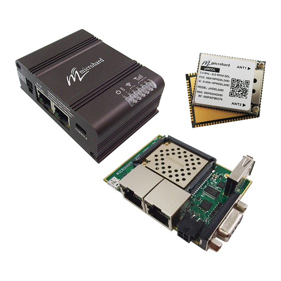
1.0 Overview The pMDDL is a feature rich, high power, 2x2 MIMO Wireless OEM Digital Data Link. The pMDDL is designed to provide high performance wireless capabilities in a compact and rug- ged OEM module for system integration. The pMDDL features simultaneous dual 10/100 Ethernet &... -
Page 11: Specifications
For detailed specifications, please see the specification sheets available on the Microhard website @ http:///www.microhardcorp.com for your specific model. Electrical/General Frequency: pMDDL2350: 2.304 - 2.390 GHz pMDDL2450: 2.402 - 2.482 GHz pMDDL2550: 2.500 - 2.570 GHz Link Rate: See Section 1.3 Performance Specifications... - Page 12 1.0 Overview Environmental Operation Temperature: -40 F(-40 C) to 185 F(85 Humidity: 5% to 95% non-condensing Mechanical Dimensions: OEM: 1.05” (26.5mm) X 1.3” (33mm) X 0.13” (3.5mm) ENC: 3.05” (77mm) X 2.2” (55mm) X 1.1” (28mm) Weight: OEM: Approx. 7 grams ENC: Approx.
-
Page 13: Pmddl Performance
1.0 Overview 1.3 Performance Specifications MIMO (2X2) ON Modulation IPerf Throughput Throughput @ Maximum Total Tx (Mbps) Sensitivity (dBm) Power (dBm) +/- 1dB 8 MHz Channel Bandwidth BPSK_1/2 -99.5 30dBm QPSK_1/2 30dBm QPSK_3/4 30dBm 16QAM_1/2 11.6 30dBm 16QAM_3/4 17.1 30dBm 64QAM_2/3 22.8 30dBm... -
Page 14: Quick Start
2.0 Quick Start This QUICK START guide will walk you through the setup and configuration of a few basic applications. The QUICK START will rely on the WebUI for configuration. This walkthrough also assumes the units used are installed in microhard interface/ development boards or custom boards that allow access to the LAN port. - Page 15 2.0 Quick Start ✓ The pMDDL will then ask for a Username and Password. Enter the factory de- faults listed below. The Factory default login: User name: admin Password: admin The factory default login: Once successfully logged in for the first User name: admin time, the pMDDL will force a password Subnet: admin...
-
Page 16: Simple Master And Slave (Auto - Using Defaults)
2.0 Quick Start 2.2 Simple Master and Slave - Auto (Using Defaults) This Quick Start example requires (2) pMDDL units, one will be configured as a Master (M), the second unit will be configured as a Slave/Remote (S). This example will use factory defaults to set up each unit so that a simple network will be estab- lished. -
Page 17: Simple Master And Slave (Manual)
2.0 Quick Start Simple Master and Slave — Manual Setup This Quick Start example requires (2) pMDDL units, one will be configured as a Master (M), the second unit will be configured as a Slave/Remote (S). This example will show the basic steps required to set up each unit so that a simple network will be established. - Page 18 2.0 Quick Start 2.3.1 Configuring the Master (Con’t) ✓ Configure the pMDDL as a Master Select Wireless from the top/main navi- gation, and then from the submenu list. In the RF Configuration ensure the Compatibility Mode, Channel Bandwidth Channel- Frequency are set the same on each module.
-
Page 19: Configuring The Slave/Remote
2.0 Quick Start 2.3.2 Configuring the Slave/Remote The following procedure describes the steps required to set up a pMDDL unit as a Slave (S). A Slave provides a single wireless connection (i.e to an Master) and pro- vides a wired connection to a PC or other devices. Section 2.1 Getting Started to connect, power up and log in to a second ✓... - Page 20 2.0 Quick Start 2.3.3 Configuring the Slave/Remote (Con’t) ✓ Configure the pMDDL as a Slave Select Wireless from the top/main navi- gation, and then from the submenu list. In the RF Configuration ensure the Compatibility Mode, Channel Bandwidth Channel- Frequency are set the same on each module.
-
Page 21: Testing The Connection
2.0 Quick Start 2.3.3 Testing the Connection ✓ Visually check to see if the pMDDL units are communicating. RSSI LED’s represent signal strength, the more LED’s that are illuminated, the stronger the signal. The Wireless > Status window also has a Connection Status sec- tion similar to that seen below: RSSI LED’s that are ‘cycling’... -
Page 22: Hardware Features
3.0 Hardware Features 3.1 pMDDL OEM Module The pMDDL modems are available as OEM modules for complete integration into custom designs. The OEM module supplies all the required raw signals to allow the unit to be tightly integrated into applications to efficiently maximize space and power requirements. The Microhard development board can provide a convenient evaluation platform to test and design with the module. -
Page 23: Mechanical Drawings
3.0 Hardware Features 3.1.1 Mechanical Drawings The pMDDL OEM Modules have an extremely small form factor as seen below. 2.79 2.79 0.80 Detail 1.27 1.18 26.5 1.50 3.41 22.35 Ground Plane 30.01 28.70 Detail 2.16 Bottom View 19.85 See Notes Ground plane must be connected to GND for required heat dissi- pation. -
Page 24: Recommended Solder Mask (Pad Landing)
3.0 Hardware Features 3.1.2 Recommended Solder Mask (Pad Landing) 22.35 0.99 30.02 28.70 34.34 Detail 19.86 27.99 Detail 0.81 Units: millimeters 1.27 1.83 Drawing 3-2: pMDDL Recommended Solder Mask © Microhard... -
Page 25: Recommended Solder Paste Pattern
3.0 Hardware Features 3.1.3 Recommended Solder Paste Pattern 19.91 2.18 34.39 30.07 Detail 28.04 Detail Units: millimeters Detail Detail 4.12 1.03 1.88 1.00 2.55 0.86 1.27 3.38 3.50 Drawing 3-3: pMDDL Recommended Solder Paste 3.1.4 OEM Connectors Antenna All pMDDL OEM Modules use an UFL connector for the antenna connection. Data The interface to the pMDDL OEM module is a tight integration using 80 pad SMT connections. -
Page 26: Smt Temperature Profile
3.0 Hardware Features 3.1.5 SMT Temperature Profile =255 2.42( C/s) 180.0 60~100s 120s 120.0 60.0 Drawing 3-4: pMDDL Reflow Profile Temperature Zone Time Parameter Zone Temperature ( Preheat zone: Heating rate: C - 165 C/s-2 Soak Zone: 60 - 100s (165 C - 217 Reflow zone:... -
Page 27: Heat Dissipation
3.0 Hardware Features 3.1.7 Heat Dissipation For optimal performance it is important to include adequate heat dissipation strategies that incorporate a heat sink or fan into any designs that integrate the pMDDL OEM module (also required for designs that utilize the optional socket). Below are two recommended heat dissipation strategies: Heat Sink (w/Thermal Gap Filler) Heat Sink -... -
Page 28: Oem Pin Descriptions
3.0 Hardware Features 3.1.8 pMDDL OEM Pin Descriptions Ant 1 Ant 2 ETH0 LINK_LED (LAN) RX_P0 (LAN) RX_N0 (LAN) TX_N0 (LAN) TX_P0 (LAN) CPU STATUS LED pMDDL ETH_BIAS (Top View) USB_MODE CONFIG RESET ETH4 LINK_LED (WAN) USBA_DP USBA_DM RSSI LED1 RSSI LED2 TX_P4 (WAN) RSSI LED3... - Page 29 3.0 Hardware Features Pin Name Description 1,17,25-26,39- Ground reference for logic, radio, and I/O pins. 40,65-80 2,3,4,5,6 Reserved for factory use only. 7,8,9,10,12,27, 33,35,36,37,38, *Currently Not Supported. For Future Expansion* 45,46,47,48,50, 51,52,53,54,59 CPU STATUS 11 Active high output indicates CPU/Module status. Active high, cannot drive LED directly.
-
Page 30: Usb Device Mode
3.0 Hardware Features Pin Name Description RX_N4 Ethernet Port 4 (WAN) Receive Pair RX_P4 TX_N4 Ethernet Port 4 (WAN) Transmit Pair TX_P4 ETH4 LINK_LED 49 Active high output indicates Ethernet port 4 link status. Active high, cannot drive LED directly. Requires current limiting resistor. 8mA maximum. TX_P0 Ethernet Port 0 (LAN) Transmit Pair TX_N0... -
Page 31: Pmddl Enclosed
3.0 Hardware Features 3.2 pMDDL Enclosed The pMDDL-ENC is a robust and compact enclosed unit that provides easy access to all the standard interfaces for connecting and working with the pMDDL. The enclosed model is ideal for base stations and applications where a full integration is not required and the modem can be used right out of the box with only software configuration required. -
Page 32: Mechanical Drawings
3.0 Hardware Features 3.2.1 pMDDL-ENC Mechanical Drawings Drawing 3-7: pMDDL-ENC Mechanical © Microhard... -
Page 33: Connectors & Indicators
3.0 Hardware Features 3.2.2 pMDDL-ENC Connectors & Indicators Ant 1 Ant 2 (3x RP-SMA Female) RSSI LEDs TX/RX LEDs RS485 LED CPU/Status DE9 Female Serial Figure 3-1: pMDDL-ENC Top View Antennas: The pMDDL-ENC module uses a RP-SMA Female connectors. ANT1 and ANT2 are marked on the Enclosure. - Page 34 3.0 Hardware Features Figure 3-2: pMDDL-ENC Back View Ethernet LAN: The Ethernet LAN port is a standard RJ45 port to connect local network devices. The default IP address for this port is 192.168.168.1. Ethernet WAN: The Ethernet WAN port is a standard RJ45 Port that can be used as a separate WAN port for Router functions, or can be bridged (via software) to the LAN as a additional switch port for local devices.
- Page 35 3.0 Hardware Features Figure 3-3: pMDDL-ENC End View CFG/RESET Button: The Config button on the pMDDL can be used to either reset the modem into its factory default configuration, or it can be used to perform a firmware recovery procedure. Factory Default Settings: While power is applied and the pMDDL in an operational state, press and hold the Config Button for more than 10 seconds to reset to a factory default Master, alternatively hold the button for 5 seconds for a factory default Slave.
-
Page 36: Pmddl Development Board
3.0 Hardware Features 3.3 pMDDL Development Board The pMDDL Development board provides a platform in which to test and evaluate the operation of the pMDDL without the need to design a custom interface PCB right from the start. The pMDDL includes a socket to insert the pMDDL and provides standard interfaces/indicators for: - Ethernet (RJ45 x2) - RS232 Serial Port... -
Page 37: Mechanical Drawings
3.0 Hardware Features 3.3.1 pMDDL Development Board Mechanical Drawings Drawing 3-8: pMDDL Development Board Mechanical Drawings © Microhard... -
Page 38: Connectors & Indicators
3.0 Hardware Features 3.3.2 pMDDL Development Board Connectors & Indicators Figure 3-4: pMDDL Development Board Antennas: The pMDDL OEM module uses a UFL connectors, Ensure proper orientation as seen above to prevent damage to the pMDDL module and to the development board. ANT1 and ANT2 are marked on the module. Ethernet LAN: The Ethernet LAN port is a standard RJ45 port to connect local network devices. - Page 39 3.0 Hardware Features Config Button: The Config button on the pMDDL can be used to either reset the modem into its factory default configuration, or it can be used to perform a firmware recovery procedure. Factory Default Settings: While power is applied and the pMDDL in an operational state, press and hold the Config Button for more than 10 seconds to reset to a factory default Master, alternatively hold the button for 5 seconds for a factory default Slave.
-
Page 40: Configuration
4.0 Configuration 4.0 Web User Interface Image 4-0-1: WebUI Initial configuration of an pMDDL using the Web User (Browser) Interface (Web UI) method involves the The factory default network following steps: settings: IP: 192.168.168.1 • configure a static IP Address on your PC to match the default subnet or if your PC is configured for Subnet: 255.255.255.0 DHCP, simply connect a PC to the LAN port of the pMDDL and it will be assigned a IP address automatically. -
Page 41: Logon Window
4.0 Configuration 4.0.1 Logon Window Upon successfully accessing the pMDDL using a Web Browser, the Logon window will appear. Image 4-0-2: Logon Window For security, do not allow the web browser to remember the User Name or Password. The factory default User Name is: admin The default password is: admin... -
Page 42: System
4.0 Configuration 4.1 System The main category tabs located at the top of the navigation bar separate the configuration of the pMDDL into different groups based on function. The System Tab contains the following submenus: • Summary Status summary of entire radio including network settings, version information, and radio connection status. -
Page 43: Settings
4.0 Configuration 4.1.2 System > Settings System Settings Options available in the System Settings menu allow for the configuration of the Host Name, Description, Console Timeout, System Log server and System Time settings. Image 4-1-2: System Settings > System Settings Host Name The Host Name is a convenient identifier for a specific pMDDL unit. -
Page 44: Date/Time
4.0 Configuration CFG Reset to Default Button Enabled by default, when the CFG button on the front of the pMDDL is held Values (Selection) down for 10s while the unit is powered up, the unit will reset and all settings will be reset to factory defaults. - Page 45 4.0 Configuration Date (yyyy-mm-dd) The calendar date may be entered in this field. Note that the entered Values value is lost should the pMDDL lose power for some reason. 2016-01-12 (varies) Time The time may be entered in this field. Note that the entered value is (hh:mm:ss) Values lost should the pMDDL lose power for some reason.
-
Page 46: Services
4.0 Configuration 4.1.3 System > Services Certain services in the pMDDL can be disabled or enabled for either security considerations or resource/ power considerations. The Enable/Disable options are applied after a reboot and will take affect after each start up. Image 4-1-4: System >... -
Page 47: Maintenance
4.0 Configuration 4.1.4 System > Maintenance Firmware Upgrade Occasional firmware updates may be released by Microhard Systems which may include fixes and/or new features. The firmware can be updated wirelessly using the WebUI. Image 4-1-5: Maintenance > Firmware Upgrade Erase Current Configuration Choose to keep or erase the current configuration. -
Page 48: Backup & Restore Configurations
4.0 Configuration Security for Configurations / Backup & Restore Configuration The configuration of the pMDDL can be backed up to a file at any time using the Backup Configuration feature. The file can the be restored using the Restore Configuration feature. It is always a good idea to backup any configurations in case of unit replacement. -
Page 49: Reboot
4.0 Configuration 4.1.5 System > Reboot The pMDDL can be remotely rebooted using the System > Reboot menu. As seen below a button ‘Reboot Now’ is provided. Once pressed, the unit immediately reboots and starts its boot up procedure. An automatic Scheduled Reboot (up to 3) can also be configured to force the pMDDL to reboot daily, weekly or monthly. -
Page 50: Network
4.0 Configuration 4.2 Network 4.2.1 Network > Status The Network Summary display gives a overview of the currently configured network interfaces including the Connection Type (Static/DHCP), IP Address, Net Mask, Default Gateway, DNS, and IPv4 Routing Table. Image 4-2-1: Network > Network Status ©... -
Page 51: Lan
4.0 Configuration 4.2.2 Network > LAN LAN Port Configuration The LAN Ethernet port(s) on the pMDDL are for connection of devices on a local network. By default, this port has a static IP Address. It also, by default is running a DHCP server to provide IP Addresses to devices that are connected to the physical LAN port (directly or via a switch). - Page 52 4.0 Configuration IGMP Snooping Enable or disable IGMP snooping on the pMDDL. IGMP snooping is Values (selection) the process of listening to Internet Group Management Protocol traffic. This allows the pMDDL to listen in on the IGMP conversations between network devices. The pMDDL then maintains a map of which The factory default links need which IP multicast streams.
-
Page 53: Lan Dhcp
4.0 Configuration LAN DHCP A pMDDL may be configured to provide dynamic host control protocol (DHCP) service to all attached (either wired or wireless devices. By default the DHCP service is enabled, so devices that are connected to the physical Ethernet LAN ports, as well as any devices that are connected by Wireless will be assigned an IP by the pMDDL. - Page 54 4.0 Configuration Preferred DNS Server Specify a preferred DNS server address to be assigned to DHCP Values (IP Address) devices. DNS: Domain Name Service (IP Address) is an Internet service that translates easily- remembered domain names Alternate DNS Server into their not-so-easily- remembered IP addresses.
-
Page 55: Wan
4.0 Configuration 4.2.3 Network > WAN WAN Configuration The WAN configuration refers to the wired WAN connection on the pMDDL. The WAN port can be used to connect the pMDDL to other networks, the internet and/or other network resources. Image 4-2-6: Network > WAN Configuration Working Mode Values (selection) Use this to set the function of the physical WAN port. - Page 56 4.0 Configuration Default Gateway If the pMDDL is integrated into a network which has a defined Values (IP Address) gateway, then, as with other hosts on the network, this gateway’s IP address will be entered into this field. If there is a DHCP server on the (no default) network, and the Connection Type (see previous page) is selected to be DHCP, the DHCP server will populate this field with the appropriate...
-
Page 57: Usb
In USB device mode, there are two functions supported, RNDIS/CDC Ethernet and CDC Serial port, when connected a host machine (PC etc). RDNIS Ethernet and CDC Serial composite drivers are available from Microhard Systems. Image 4-2-7: Network > USB... -
Page 58: Dhcp (Mac Binding)
4.0 Configuration 4.2.5 Network > DHCP Static IP Addresses (for DHCP Server) In many applications it is required to know the IP address of connected devices in order to implement security and firewall rules as well as for Port Forwarding rules. The Static IP Address (for DHCP Server) features MAC binding to allow connected devices to automatically obtain a specific IP address. -
Page 59: Routes
4.0 Configuration 4.2.6 Network > Routes Static Routes Configuration It may be desirable to have devices on different subnets to be able to talk to one another. This can be accomplished by specifying a static route, telling the pMDDL where to send data. Image 4-2-9: Network >... - Page 60 4.0 Configuration Metric In some cases there may be multiple routes to reach a destination. Values (Integer) The Metric can be set to give certain routes priority, the lower the metric is, the better the route. The more hops it takes to get to a destination, the higher the metric.
-
Page 61: Ports
4.0 Configuration 4.2.7 Network > Ports The Network > Ports menu can be used to determine the characteristics of the physical Ethernet interfaces on the pMDDL. As seen below the Mode (Auto/Manual), Auto-Negotiation, Speed (10/100Mbit/s) and the Duplex (Full/Half) can all be configured on the pMDDL. Image 4-2-10: Network >... -
Page 62: Device List
4.0 Configuration 4.2.8 Network > Device List The Network > Device List shows the current ARP table for the local network adapter. The MAC address and IP address are shown, however not only DHCP assigned devices are listed in the device list, any devices, even those statically assigned, that are connected through the local network interface (s) are displayed, including those connected through a hub or switch. -
Page 63: Wireless
4.0 Configuration 4.3 Wireless 4.3.1 Wireless > Status The Status window gives a summary of all radio or wireless related settings and connections. The General Status section shows the MAC address of the current radio, the Operating Mode (Master, Slave etc), the Network ID being used, the Compatibility Mode, Channel Bandwidth and frequency information and the type of security used. -
Page 64: Radio1
4.0 Configuration 4.3.2 Wireless > RF RF Configuration The RF Configuration allows for the configuration of the radio module. You can turn the radio on or off, adjust the TX power, select the channel bandwidth and frequency, as well as the operating mode of the radio as seen below. -
Page 65: Channel Bandwidth
Values (MHz) network. The frequency shown is the center frequency and is available in 1 MHz increments, values shown will vary with the Channel pMDDL2350: 2304 - 2390 MHz Bandwidth selected above. pMDDL2450: 2405 - 2479 MHz pMDDL2550: 2500 - 2570 MHz... -
Page 66: Operating Mode
4.0 Configuration Mode Values (selection) Master - A Master may provide a wireless data connection to many slaves/remotes. Master Slave/Remote - A Salve may sustain one wireless connection, Slave i.e. to an Master. Relay (Future) For video applications it is required to connect the video source (camera) to the radio designated as the Master. -
Page 67: Network Id
4.0 Configuration Extended Addressing Enable or disable extended addressing. Values (selection) For multicast traffic sending from the Master to multiple receivers, it is On / Off recommended to configure the system with “Extended Addressing” disabled and also select a proper multicast rate defined by the link budget. -
Page 68: Firewall
4.0 Configuration 4.4 Firewall 4.4.1 Firewall > Summary The Firewall Summary allows a user to see detailed information about how the firewall is operating. The All, Filter, Nat, Raw, and Mangle options can be used to view different aspects of the firewall. Image 4-4-1: Firewall >... -
Page 69: General
4.0 Configuration 4.4.2 Firewall > General The General Firewall settings allow users to enable or disable the firewall, and to decide which areas of the modem to protect. The Firewall can also be reset to factory defaults from this area of the WebUI. Image 4-4-2: Firewall >... -
Page 70: Port Forwarding
4.0 Configuration 4.4.3 Firewall > Port Forwarding The pMDDL can be used to provide remote access to connected devices. To access these devices a user must define how incoming traffic is handled by the pMDDL. If all incoming traffic is intended for a specific connected device, DMZ could be used to simplify the process, as all incoming traffic can be directed towards a specific IP address. - Page 71 4.0 Configuration Exception Port Enter a exception port number that will NOT be forwarded to the DMZ Values (Port #) server IP. Usually a configuration or remote management port that is excluded to retain external control of the pMDDL. Up to 15 ports can be specified using list (port1, port2, etc) or by port range (start: stop) Firewall Port Forwarding Configuration Name...
-
Page 72: Mac-Ip List
4.0 Configuration 4.4.4 Firewall > MAC-IP List MAC List configuration can be used to control which physical LAN devices can access the ports on the pMDDL, by restricting or allowing connections based on the MAC address. IP List configuration can be used to define who or what can access the pMDDL, by restricting or allowing connections based on the IP Address/Subnet. - Page 73 4.0 Configuration Firewall MAC List Configuration (Continued) Action The Action is used to define how the rule handles the connection request. Values (selection) ACCEPT will allow a connection, while REJECT (error) and DROP (quietly ACCEPT dropped), will refuse connections. DROP REJECT Firewall IP List Configuration Rule Name...
-
Page 74: Rules
4.0 Configuration 4.4.5 Firewall > Rules The Rules configuration can be used to define specific rules on how local and remote devices access different ports and services. MAC List and IP List are used for general access, and are applied before rules are processed. - Page 75 4.0 Configuration Source IPs Match incoming traffic from the specified source IP range. Boxes accept Values (IP Address) single IP Addresses without network masks, example: 192.168.1.0 to 192.168.1.255 represents all IP Addresses in the 192.168.1.0/24 network. 192.168.0.0 to (Put same IP in both boxes for a single IP match.) 192.168.0.0 Destination Select the zone which is the intended destination of the data traffic.
-
Page 76: Default
4.0 Configuration 4.4.6 Firewall > Default The firewall can be returned to default setting without requiring the entire modem to be reset to defaults. It is recommended to restart the modem once changes to the firewall or a reset is performed. Image 4-4-6: Firewall >... -
Page 77: Serial
4.0 Configuration 4.5 Serial 4.5.1 Serial > Summary The Serial > Summary window gives a summary of the on board serial data port. A second serial port can be added to the pMDDL OEM by interfacing a FTDI USB to Basic UART IC as shown in Appendix D: Serial Port Extension. -
Page 78: Rs232 Port Settings
4.0 Configuration 4.6.2 Serial > Settings This menu option is used to configure the serial device server for the serial communications port. Serial device data may be brought into the IP network through TCP, UDP, or multicast; it may also exit the pMDDL network on another pMDDL serial port. -
Page 79: Data Baud Rate
4.0 Configuration Port Status Select operational status of the Serial Port. The port is in console Values (selection) mode by default. Data / Console Escape Sequence Enabling the escape sequence allows users to temporarily exit data Values (selection) mode and enter console mode for the serial port. Enabled / Disabled Escape Guard Interval Values (seconds) - Page 80 4.0 Configuration Data Mode Values (selection) This setting defines the serial output data framing. In Transparent mode (default), the received data will be output promptly from the pMDDL. Seamless / Transparent When set to Seamless, the serial port server will add a gap between data frames to comply with the MODBUS protocol for example.
-
Page 81: Ip Protocol Config
4.0 Configuration IP Protocol Config This setting determines which protocol the serial server will use to Values (selection) transmit serial port data over the pMDDL network. TCP Client The protocol selected in the IP Protocol Config field will determine TCP Server which configuration options appear in the remainder of the RS232 TCP Client/Server Configuration Menu. -
Page 82: Tcp Client/Server
4.0 Configuration IP Protocol Config (Continued…) TCP Client/Server: In this mode, the pMDDL will be a combined TCP Client and Server, meaning that it can both initiate and serve TCP connection (session) requests. Refer to the TCP Client and TCP Server descriptions and settings described previously as all information, combined, is applicable to this mode. -
Page 83: Ppp
4.0 Configuration IP Protocol Config (Continued…) PPP: The serial port can be configured as a PPP server for a serial connection with a PC or other device. The attached PC could then use a dedicated serial (WindowsXP - dialup/modem) type PPP connection to access the network resources of the pMDDL. -
Page 84: Gs0 (Usb - Device Mode)
4.0 Configuration 4.6.3 Serial > GS0 This tab only appears if the pMDDL has been set to operate as a USB Device (Pin 14 connected to GND through a 1k resisitor). Microhard USB Serial Composite Drivers are available which allow the pMDDL to appear as a serial device to a USB Host (PC etc.) The USB port can be set to “Idle”... -
Page 85: Diag
4.0 Configuration 4.6 Diag 4.6.1 Diag > Ping The Network Tools Ping feature provides a tool to test network connectivity from within the pMDDL unit. A user can use the Ping command by entering the IP address or host name of a destination device in the Ping Host Name field, use Count for the number of ping messages to send, and the Packet Size to modify the size of the packets sent. -
Page 86: Iperf
4.0 Configuration 4.6.3 Diag > Iperf The pMDDL features an integrated Iperf server/client to use to measure and analyze throughput of TCP/ UDP packets to and/or from the pMDDL. Iperf is a 3rd party utility that can be loaded on any PC to measure network performance. -
Page 87: Usb Tethering
4.0 Configuration 4.6.4 Diag > USB Tethering The pMDDL can be Tethered to certain Android Mobile Devices to view a video stream from a remote video encoder. This is a preliminary feature that has limited support at this time. Contact Microhard for more information. -
Page 88: Admin
4.0 Configuration 4.7 Admin 4.7.1 Admin > Users Password Change The Password Change menu allows the password of the user ‘admin’ to be changed. The ‘admin’ username cannot be deleted, but additional users can be defined and deleted as required as seen in the Users menu below. - Page 89 4.0 Configuration Add Users Different users can be set up with customized access to the WebUI. Each menu or tab of the WebUI can be disabled on a per user basis as seen below. Image 4-7-2: Access Control > Users Username Enter the desired username.
-
Page 90: Snmp
The pages that follow describe the different fields required to set up SNMP on the pMDDL. MIBS may be requested from Microhard Systems Inc. The MIB file can be downloaded directly from the unit using the ‘Get MIB File’ button on the Network >... - Page 91 4.0 Configuration SNMP Settings Image 4-7-3: Admin > SNMP SNMP Agent Status If disabled, an SNMP service is not provided from the device. Values (selection) Enabled, the device - now an SNMP agent - can support SNMPv1, v2, & v3. Disable / Enable Read Only Community Name Effectively a plain-text password mechanism used to weakly...
- Page 92 4.0 Configuration SNMP Version Select the SNMP version used. Only SNMP version 1 & 2 support Values (selection) SNMP traps (See MIB). Version 1 / Version 2 / Version 3 SNMP V3 User Name Values (string) Defines the user name for SNMPv3. V3user V3 User Read Write Limit Defines accessibility of SNMPv3;...
- Page 93 4.0 Configuration SNMP Trap Settings Image 4-7-4: Admin > SNMP Trap Settings SNMP Trap Status Values (selection) Enable or disable autonomous SNMP traps from the device. Disable / Enable Trap Community Name Effectively a plain-text password mechanism used to weakly Values (string) authenticate SNMP queries.
- Page 94 4.0 Configuration WAN IP Values (selection) Enable or Disable WAN IP Traps. Device will send a trap any time the WAN IP has been changed. Generally used with dynamic IP addresses. Disable / Enable © Microhard...
-
Page 95: Discovery
4.0 Configuration 4.7.3 Admin > Discovery Server Status Settings Microhard Radios employ a discovery service that can be used to detect other Microhard devices on a network. This can be done using a stand alone utility from Microhard System’s called ‘IP Discovery’ or from the Tools >... -
Page 96: Logout
4.0 Configuration 4.7.4 Admin > Logout The logout function allows a user to end the current configuration session and prompt for a login screen. Image 4-7-6: Admin > logout © Microhard... -
Page 97: At Command Line Interface
5.0 AT Command Line Interface 5.1 AT Command Overview AT Commands can be issued to configure and manage the pMDDL, via TCP/IP (telnet). 5.1.1 Telnet (TCP/IP) Telnet can be used to access the AT Command interface of the pMDDL. The default port is TCP Port 23. A telnet session can be made to the unit using any Telnet application (Windows Telnet, Tera Term, ProComm etc). -
Page 98: At Command Syntax
5.0 AT Command Line Interface 5.2 AT Command Syntax The follow syntax is used when issuing AT Commands on the pMDDL All commands start with the AT characters and end with the <Enter> key Microhard Specific Commands start with +M Help will list top level commands (ATL will list ALL available AT Commands) To query syntax of a command: AT+<command_name>=? Syntax for commands that are used only to query a setting:... -
Page 99: Supported At Commands
5.0 AT Command Line Interface 5.3 Supported AT Commands Basic AT Commands AT Command Description Syntax Effect AT echo OK AT <enter> Immediate ATE0 Disable echo ATE0 <enter> Immediate ATE1 Enabled local echo ATE1 <enter> Immediate Show a list of previously run commands ATH <enter>... - Page 100 5.0 AT Command Line Interface Administrative AT Commands (Continued) AT Command Description Syntax Effect AT+MASNMPTRAP Get/Set SNMP Trap AT+MASNMPTRAP[=<Mode>[,<Name>,<IP>[,<AuthFailureTraps>]] AT&W <Mode>: 0 - Disable 1 - Enable <Name>: Trap Community Name. 1 to 32 characters <IP>: Trap Manage Host IP. Default 0.0.0.0 (Disable) <AuthFailureTraps>: 0 - Disable 1 - Enable...
- Page 101 5.0 AT Command Line Interface Serial Port AT Commands (Continued) AT Command Description Syntax Effect AT+MCIPM2 Get/Set Serial port IP protocol mode AT+MCIPM2=<IP Protocol Config> AT&W Parameters: COM2 IP Protocol Config: 0 - TCP Client 1 - TCP Server 2 - TCP Client/Server 3 - UDP Point to Point 4 - UDP Point to Multipoint(P) 5 - UDP Point to Multipoint(MP)
- Page 102 5.0 AT Command Line Interface Firewall AT Commands AT Command Description Syntax Effect AT+MFGEN Get/Set firewall general configuration AT+MFGEN[=<Config>[,<Mode>]] AT&W Parameters Config : 0 - WAN Remote Management 1 - WAN Request 2 - LAN to WAN Access Control 3 - Anti-Spoof 4 - Packet Normalization Mode : 0 - Disable (Block) 1 - Enable (Allow)
- Page 103 5.0 AT Command Line Interface Firewall AT Commands (Continued) AT Command Description Syntax Effect AT+MFRULE Get/Set firewall rule AT+MFRULE[=<Name>[,<Operation>[,<Action>,<Source>,<Src IP Format>,<Src IP From/Subnet AT&W >, <Src IP To/Prefix>, <Destination>,<Dest IP Format>,<Dest IP From/Subnet>,<Dest IP To/ Prefix>, <Dest Port>,<Protocol>]]] Parameters: Name : Name of firewall rule name, 1 - 64 characters Operation : ADD - Add a firewall rule...
- Page 104 5.0 AT Command Line Interface Network AT Commands (Continued) AT Command Description Syntax Effect AT+MNLANSTP Get/Set the network LAN inetrafce: Spanning AT+MNLANSTP=<LAN Name>[,<STP>] AT&W Tree (STP) Parameters: LAN Name : Name of Network LAN interface Spanning Tree : 0 - Off 1 - On AT+MNLANIGMP Get/Set the network LAN interface: IGMP Snoop-...
- Page 105 5.0 AT Command Line Interface Network AT Commands (Continued) AT Command Description Syntax Effect AT+MNIPMAC Show/Add/Delete/Release/ReleaseAll the MAC-IP AT+MNIPMAC[=<Operation>[,<Name>[,<IP Address>,<MAC Address>]]] AT&W address binding Usage: AT+MNIPMAC AT+MNIPMAC=SHOW,<Name> AT+MNIPMAC=ADD,<Name>,<IP Address>,<MAC Address> AT+MNIPMAC=DEL,<NAME> AT+MNIPMAC=RELEASE,<NAME> AT+MNIPMAC=RELEASEALL Parameters: Operation : SHOW - Show the details of the MAC-IP address binding ADD - Add a new MAC-IP address binding DEL - Delete an existing MAC-IP address binding RELEASE - Release the active DHCP lease...
- Page 106 5.0 AT Command Line Interface Network AT Commands (Continued) AT Command Description Syntax Effect AT+MNUSB Show/Edit the network USB Interface AT+MNUSB[=<Mode>[,<Protocol>[,<IP>,<Netmask>[,<Gateway>]]]] AT&W Usage: AT+MNUSB AT+MNUSB=<Mode>,<Protocol>,<IP>,<Netmask>[,<Gateway>] Where <Mode>=0 and <Protocol>=0 AT+MNUSB=<Mode>,<Protocol> Where <Mode>=0 and <Protocol>=1 AT+MNUSB=<Mode> Where <Mode>=1/2 Parameters: Mode : 0 - Independent LAN 1 - Bridge with LAN Port 2 - Bridge with WAN Port Protocol: 0 - Static IP...
- Page 107 5.0 AT Command Line Interface System AT Commands AT Command Description Syntax Effect AT+MSCNTO Get/Set the console timeout AT+MSCNTO=<Timeout_s> AT&W Parameter: <Timeout_s> : 30 to 65535 in seconds, 0-Disable AT+MSPWD Set password AT+MSPWD=<New Password>,<Confirm Password> AT&W Parameters: <New Password> : 5-64 characters except space <Confirm Password>...
- Page 108 5.0 AT Command Line Interface Wireless (Radio) AT Commands AT Command Description Syntax Effect AT+MWRADIO Get/Set radio status, On or Off AT+MWRADIO[=<Radio>] AT&W <Radio> 0 - Off 1 - On AT+MWDISTANCE Get/Set radio Wireless Distance AT+MWDISTANCE[=<Distance>] AT&W <Distance> 1 - 200000 in meter AT+MWTXPOWER Get/Set radio Tx power AT+MWTXPOWER[=<Tx Power>]...
- Page 109 5.0 AT Command Line Interface Wireless (Radio) AT Commands (Continued) AT Command Description Syntax Effect AT+MWEXTADDR Get/Set radio extended addressing AT+MWEXTADDR[=<Extended Addressing>] AT&W <Extended Addressing> : 0 - Off 1 - On AT+MWNETWORKID Get/Set radio Network ID AT+MWNETWORKID[=<Network ID>] AT&W <Network ID>...
-
Page 110: Installation
6.0 Installation The are a number of factors to consider when preparing to deploy a radio network, several of which have been touched-upon or detailed elsewhere within this manual. Following is a listing of a number of factors, in no particular order: Network Topology The pMDDL currently supports Master and Slave modes which can create either Point to Mul- tipoint or Point to Point network topologies. - Page 111 The channel selection of the pMDDL often allows it to work well in an environment within which there may be sources of in-band interference. Cavity filters are also available if required: con- tact Microhard Systems Inc. for further information. © Microhard...
-
Page 112: Path Calculation
6.0 Installation 6.1 Path Calculation Assuming adequate antenna heights, a basic formula to determine if an adequate radio signal path exists (i.e. there is a reasonable fade margin to ensure reliability) is: Fade Margin = System Gain - Path Loss FCC regulations where all values are expressed in dB. -
Page 113: Installation Of Antenna System Components
6.0 Installation Distance (km) Master Height (m) Remote Height (m) Path Loss (dB) 116.5 110.9 124.1 117.7 135.3 128.9 116.2 109.6 122.4 128.8 Table 6-1: Path Loss satisfy radio frequency (RF) exposure 6.2 Installation of Antenna System Components requirements mobile transmitting devices, separation distance of 23cm... -
Page 114: Antenna Selection, Placement & Orientation
6.0 Installation 6.2.2 2X2 MIMO Antenna Selection, Placement & Orientation For optimal performance of the pMDDL modems one must consider and plan for the specific ap- plication and environment where the pMDDL modules will be used. Described below are some of the considerations that must be taken into account while using pMDDL modems. -
Page 115: Coaxial Cable
Paging towers and cellular base stations in close prox- To comply with FCC imity to the pMDDL’s antenna can desensitize the receiver. Microhard Systems Inc.’s external regulations, the maximum cavity filter eliminates this problem. The filter has two N-female connectors and should be con- EIRP must not exceed nected inline at the interface to the RF equipment. -
Page 116: Appendices
Appendix A: Serial Interface Module Host (e.g. PC) (DCE) (DTE) Arrows denote the direction that signals are asserted (e.g., DCD originates at the Signal DCE, informing the DTE that a carrier is present). DCD → The interface conforms to standard RS-232 signals, so direct connection to a RX →... -
Page 117: Appendix B: Firmware Recovery
Appendix B: Firmware Recovery Procedure In event that your unit becomes unresponsive it may be required to perform a firmware recovery procedure outlined below: 1. Download and save firmware file in a local folder, for example C:\; 2. Separate the PC from the network and set IP to static: 192.168.1.1 255.255.255.0 3. -
Page 118: Appendix C: Sample Interface Schematic
Appendix C: Sample Interface Schematic © Microhard... -
Page 119: Appendix D: Serial Port Extension
Appendix D: Serial Port Extension The pMDDL can support a second serial port by utilizing a FT234XD USB to serial UART interfaced to the USB lines of the pMDDL. The sample circuit below shows how this is done. Drawing App-D: FTDI USB to Basic UART ©... -
Page 120: Appendix E: Troubleshooting/Faq
Appendix E: Troubleshooting Below is a number of the common support questions that are asked about the pMDDL. The purpose of the section is to provide answers and/or direction on how to solve common problems with the pMDDL. __________________________________________________________________ Question: What is the default IP Address of the pMDDL? Answer: The default IP address for the LAN is 192.168.168.1. - Page 121 150 Country Hills Landing NW Calgary, Alberta Canada T3K 5P3 Phone: (403) 248-0028 Toll Free: 1-855-353-0028 www.microhardcorp.com © Microhard...
Need help?
Do you have a question about the pMDDL2350 and is the answer not in the manual?
Questions and answers