Table of Contents
Advertisement
Quick Links
ESSENCE 45 ELITE DESIGNER CLEAN FACE
30,000 BTU
Natural Gas & Propane
Installation and Operating Instructions
MODEL: ESS45
IF THE INFORMATION IN THESE INSTRUCTIONS IS NOT FOLLOWED EXACTLY, A FIRE OR
EXPLOSION MAY RESULT CAUSING PROPERTY DAMAGE, PERSONAL INJURY, OR DEATH.
Do not store or use gasoline or other flammable vapors and liquids in the vicinity of this or
WHAT TO DO IF YOU SMELL GAS:
Do not try to light any appliance
Do not touch any electrical switch; do not use any phone in your building
Immediately call your gas supplier from a neighbour's phone. Follow gas supplier's
instructions
If you cannot reach your gas supplier, call the fire department.
Installation and service must be performed by a qualified installer, service agency or gas
supplier.
WARNING: Improper installation, adjustment, alteration, services or maintenance can cause
injury or property damage. Refer to this manual. For assistance or additional information
consult a qualified installer, service agency or the gas supplier.
INSTALLER: Leave this manual with the appliance.
CONSUMER: Retain this manual for future reference.
PLEASE READ THIS MANUAL BEFORE
INSTALLING OR USING THIS APPLIANCE.
SAVE THIS MANUAL FOR FUTURE
REFERENCE.
A BARRIER DESIGNED TO REDUCE THE RISK OF
BURNS FROM THE HOT VIEWING GLASS IS
PROVIDED WITH THIS APPLIANCE AND SHALL BE
INSTALLED.
CLIENT # LC773211
WARNING
any other appliance.
Page 1 of 56
Advertisement
Table of Contents

Related Manuals for Savannah Heating ESSENCE ESS45


Summary of Contents for Savannah Heating ESSENCE ESS45
- Page 1 ESSENCE 45 ELITE DESIGNER CLEAN FACE 30,000 BTU Natural Gas & Propane Installation and Operating Instructions MODEL: ESS45 CLIENT # LC773211 WARNING IF THE INFORMATION IN THESE INSTRUCTIONS IS NOT FOLLOWED EXACTLY, A FIRE OR EXPLOSION MAY RESULT CAUSING PROPERTY DAMAGE, PERSONAL INJURY, OR DEATH. Do not store or use gasoline or other flammable vapors and liquids in the vicinity of this or any other appliance.
- Page 2 ESSENCE 45 DESIGNER ELITE VISAGE CLEAN 30,000 BTU GAZ NATUREL ET PROPANE Manuel D’installation et Guide de l’utilisateur CLIENT # LC773211 MODEL: ESS45 AVERTISSEMENT ASSUREZ-VOUS DE BIEN SUIVRE LES INSTRUCTIONS DONNÉES DANS CETTE NOTICE POUR RÉDUIRE AU MINIMUM LE RISQUE D'INCENDIE OU D'EXPLOSION OU POUR ÉVITER TOUT DOMMAGE MATÉRIEL, TOUTE BLESSURE OU LA MORT.
-
Page 3: Table Of Contents
Table of Contents IMPORTANT SAFETY INFORMATION …………………………………………………………….. 4 – 5 INTRODUCTION ........................Specifications, Appliance Dimensions & Installation Codes ......... 6 - 7 Features, Remote Control Functions ..............8 - 10 Intended Use ......................11 General Safety ....................11 - 12 OPERATION ........................... -
Page 4: Important Safety Information
WARNING Read this owner’s manual carefully and completely before trying to assemble, operate or service this fireplace. Follow instructions for proper installation Failure to install this appliance per the manufacturer’s instructions or failure to use only parts specifically approved with this appliance may result in property damage or personal injury. - Page 5 WARNING AVERTISSEMENT Ne pas utiliser cet appareil s’il a été plongé, Do not use this appliance if any part has meme partiellement, dans l’eau. Appeler un been under water. Immediately call a technician qualifié pour inspecter l’appareil et qualified service technician to inspect the appliance and to replace any part of the remplacer toute partie du système de control system and any gas control which...
-
Page 6: Introduction
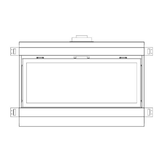
1.0 INTRODUCTION 1.1 SPECIFICATIONS TABLE 1 ITEM NATURAL GAS (NG) PROPANE (LP) MAXIMUM INPUT: Hi 30,000 Btu/hr (8.79 kW) 27,000 Btu/hr (7.91 kW) MINIMUM INPUT: Lo 22,000 Btu/hr (6.45 kW) 19,500 Btu/hr (5.71 kW) MANIFOLD PRESSURE: 3.5” w.c. (0.87 kPa) 10.0”... - Page 7 APPLIANCE DIMENSIONS 44.23” 48.28" 16.50” 50.38” INSTALLATION CODES This appliance is a Direct Vent appliance which draws all combustion air from outside the building through an intake vent pipe. Installation must conform to local codes. In the absence of local codes, installation must conform to the National Fuel Gas Code ANSI Z223.1/NFPA 54, or the current Natural Gas and Propane Installation Code CSA B149.1.
-
Page 8: Features, Remote Control Functions
1.2 FEATURES Ignition system: Standing pilot ignition system with thermopile and thermocouple flame detection and piezo igniter. Fan control * Optional * Variable speed control: For units equipped with a fan control, the knob controls the fan speed, turning the knob counter-clockwise turns it to the “Off”... - Page 9 Program Mode The Program function is controlled by the PROG/TIME button. The control may be programmed for up to two settings for weekdays and two settings for weekends. The control is preset to factory settings. When the Program Mode is activated, the unit will automatically be operating in the Thermostat Mode. The unit will turn on or off based upon room and set temperature.
- Page 10 Fan Control The unit must be ON to operate the Fan. The Fan will turn on after 5 minutes of operation. Once the Fan comes on, it can be controlled using the FAN button. Press the FAN button, and the fan icon and speed will appear on the LCD screen. Press the UP or DOWN button to control the fan speed (0-6).
-
Page 11: Intended Use
1.3 INTENDED USE / USAGE PROPOSÉ This appliance is intended to be used as a zero clearance fireplace. Cet appareil est destiné à être utilisé comme un foyer à dégagement zéro. 1.4 GENERAL SAFETY / SÉCURITÉ GÉNÉRALE Maintain adequate clearances around air openings into the combustion chamber. ... - Page 12 IMPORTANT PLEASE READ THE FOLLOWING CAREFULLY It is normal for fireplaces fabricated of steel to give off some expansion and/or contraction noises during the start up or cool down cycle. It is not unusual for gas fireplaces to give off some odors the first time they are burned. This is due to the oils and sealants in the manufacturing process.
-
Page 13: Operation
2.0 OPERATION LIGHTING INSTRUCTIONS - for Intermittent Pilot FOR YOUR SAFETY, READ BEFORE LIGHTING WARNING: If you do not follow these instructions exactly, a fire or explosion may result causing property damage, personal injury or loss of life. This appliance is equipped with an ignition device which automatically lights the pilot. Do not try to light the pilot by hand. BEFORE LIGHTING smell all around the appliance area for gas. - Page 14 INSTRUCTIONS D'ALLUMAGE - Pilote intermittent POUR PLUS DE SÉCURITÉ, LIRE AVANT D’ALLUMER AVERTISSEMENT: Quiconque ne respecte pas à la letter les instructions dans la présente notice risqué de déclencher un incendie ou une explosion entraînant des dommages, des blessures ou la mort. Cet appareil est équipé...
-
Page 15: Installation
3.0 INSTALLATION 3.1 INSTALLATION & SAFETY NOTES / NOTES D'INSTALLATION ET DE SECURITE Read all instructions before starting installation and follow them carefully during installation to ensure maximum benefit and safety. Failure to follow these instructions will void your warranty and may present a fire hazard. -
Page 16: Installation Of Non-Combustible Board
3.3.1 INSTALLING NON-COMBUSTIBLE BOARD WARNING THE SURFACE ABOVE THE APPLIANCE GETS VERY HOT. IF PROPER FINISHING MATERIALS ARE NOT USED, CRACKING CAN OCCUR. LA SURFACE AU-DESSUS DE L'APPAREIL EST TRÈS CHAUDE. SI DES MATERIAUX DE FINITION CORRESPONDANTS NE SONT PAS UTILISES, DES RISQUES PEUVENT SURVENIR. The 11.75”... -
Page 17: Minimum Clearances & Non Combustible Material Requirements
3.3.2 MINIMUM CLEARANCES / DÉGAGEMENTS 12.00” 48.25” 2.00” 6.00” 16.50” NON-COMBUSTIBLE BOARD – 11.75" (298.5mm) x 44.3125" (1125.5mm) WILL BE SUPPLIED BY MANUFACTURER AND MUST BE ATTACHED TO TOP OF FIREPLACE SEE DIAGRAM PAGE 18 MINIMUM CLEARANCES TO COMBUSTIBLES A = 58” TO INTERNAL CEILING B = 2”... - Page 18 Clearances are in accordance with local installation codes and the requirements of the gas supplier. **The mantel placement chart on this page illustrates the allowable mantel sizes and placements. The 45 degree angle can be used to determine the allowable mantel size based on the elevation above the units upper trim.
- Page 19 NON-COMBUSTIBLE BOARD 11.75 x 44.3125 SUPPLIED BY MANUFACTURER 38.75 TO BOTTOM 40.00 TO TOP OF NON- COMBUSTIBLE STUD ON BOARD FROM EDGE BOTTOM OF FIREPLACE 48.34” STUD The closest combustible material above the fireplace must be a minimum of 40.00” from the floor with the stud laying on edge as shown above.
-
Page 20: Gas Line Installation
3.3.3 GAS LINE INSTALLATION / INSTALLATION DE LA LIGNE de GAZ Install supply line using any piping approved for your installation meeting CAN/CGA 6.10, AA 3, ANSI Z21.24 or Z21.45. A qualified gas fitter should install the gas line in accordance with all local building codes. If codes permit, coiled copper tubing may be used for gas supply. -
Page 21: Direct Vent Information
3.3.4 DIRECT VENT INFORMATION / DIRECT VENT D'INFORMATION The unit must be connected to listed 2-ply aluminium venting and vent cap / termination kit, 4” flex vent on the exhaust side and listed 7” flex vent on the air intake side or can be used with Security Venting, Dura-Vent 4”... - Page 22 Figure 6 Dura-Vent or Selkirk Direct-Temp Venting The minimum vent system for horizontal termination must consist of: Dura-Vent adapter Part # W175-0053 directly on top of unit or Selkirk adapter Part #1604247B 15” (305mm) vertical length of vent 90 degree elbow 15"...
- Page 23 Security Venting The minimum vent system for horizontal termination must consist of: Dura-Vent adapter Part # W175-0053 directly on top of unit 15” (305mm) vertical length of vent 90 degree elbow 15" (305 mm) horizontal length of vent Wall thimble part #IMC1082A Horizontal termination cap SV4CHC The maximum horizontal vent system consists of: Dura-Vent adapter Part # W175-0053 directly on top of unit...
- Page 24 2-Ply Aluminum Flex Vent The minimum vent system for horizontal termination must consist of: 15” (305 mm) vertical length (measured to center of vent pipe) with a 90 degree bend and a 15” (305 mm) horizontal length (measured from center of vent pipe) Wall thimble part# IMC1082A Horizontal termination cap part # IMC1070A or IMC1070B The maximum horizontal vent system consists of:...
- Page 25 VERTICAL VENT TABLE NOTE: All vent dimensions are measured from the (All values are in feet) appliance surface where the vent connects to the point where exhaust gases exit the termination. REMARQUE: Toutes les dimensions sont mesurées à partir d'aération de la surface de l'appareil où l'évent se connecte au point où...
- Page 26 34’ 20’ 15” MINIMUM 15” MAXIMUM (Example: Where A---A = Vertical @ 2’ B---B = Horizontal @ 5’) Page 26 of 56...
- Page 27 USE OF SEALANT Sealant is required on vent system joints, except Metal-Fab Sure-Seal direct vent system joints (figure 7). On longer vent runs, especially vertical runs, sealant will ensure that the combustion air enters from outdoors, and not through the vent joints. Use high temperature sealant, available from local suppliers, on the inner pipe joint, applying the sealant around the outside of the male part of the vent.
- Page 28 Typical Dura- Vent, Security Chimney & Metal-Fab Venting Installation: Vent terminals shall not be recessed into a wall or siding. Fireplace Horizontal Wall Vent Terminations The position of the horizontal vent termination must be positioned in such a way as to meet all local building codes.
- Page 29 13.00” 10.00” Ø 9.00” ” Ø 7.00” 10.00” OUTER PIPE 7” WALL THIMBLE 9" 10 x 10 MIN OPENING VIEW OF SAFETY CAGE Mark a 10” x 10” square around the center mark (inside dimensions). Cut and frame the exterior wall to accept the wall thimble.
- Page 30 Vertical Installations Always maintain a 1” clearance around the vent pipe (vertical) and 1” clearance horizontal, when passing through ceilings, walls, roofs, enclosures, attic rafter or any combustible surfaces. DO NOT PACK AIR SPACES WITH INSULATION NE PAS PACK ESPACES D'AIR AVEC ISOLATION When passing through a flat ceiling install a Box/Wall thimble.
- Page 31 Termination above Roof Consult local codes for minimum vent cap height above the roof (X), vent must be a minimum of 2’ from any wall. To prevent water seepage; install the flashing with upper portion under the roofing material and the lower portion over the roofing material.
- Page 32 In accordance with the current CSA B149.1, Natural Gas and Propane Installation Code In accordance with the current ANSI Z223.1 / NFPA 54, National Fuel Gas Code † A vent shall not terminate directly above a sidewalk or paved driveway that is located between two single family dwellings and serves both dwellings ‡...
-
Page 33: Glass Media Installation
3.3.5 GLASS INSTALLATION / INSTALLATION DE VERRE Burn medium positions are critical to the safe and clean operation of this appliance. Never add any other material into the firebox. Use only with burn medium supplied with this unit. Burn positions moyennes sont critiques pour le fonctionnement sûr et propre de cet appareil. -
Page 34: Door Installation And Safety Screen
3.3.6 DOOR INSTALLATION / INSTALLATION DE LA PORTE Place the bottom of the door into the Bottom Door Brackets on the left and right of the firebox / Placez le bas de la porte dans les supports de porte bas à gauche et à droite de la chambre de combustion. DOOR LOCK BRACKETS BOTTOM DOOR BRACKETS Bottom door brackets are not visible in picture... - Page 35 Do not operate this appliance with the glass front removed, cracked or broken. Replacement of the glass should be done by a licensed or qualified service person. For use with glass doors certified with the appliance only Do not use any substitute materials ...
-
Page 36: Initial Firing
3.3.7 INITIAL FIRING When lit for the first few times, the appliance may emit an odor resulting from evaporation of paint and lubricants used in the manufacturing process. Open a door or window for ventilation. Anyone with a respiratory condition may need to leave the room during the initial firings. It is normal for the appliance to expand and contract while it heats up or cools down whether this is from a cold start or a steady-state condition where the fan has come on or off. -
Page 37: Altitude Adjustment
PARTS REQUIRING ADJUSTMENT DURING OPERATION MAY BE HOT. CAUTION ATTENTION PIECES NECESSITANT REGLAGE PENDANT LA MARCHE PEUT ETRE CHAUDE Factory Setting Natural Gas – open 1/8” (3.175mm) Propane Gas – Fully Open Aeration adjustment is important for the correct functioning of the appliance. Carbon build up, flame lifting or any malfunction due to improper aeration adjustment during installation is not covered under the factory warranty. - Page 38 Burner pan Pilot Box Showing the left Access Panel with burner pan removed 3/. Remove the access panels, one on either side of the pilot box / Retirer les panneaux d'accès, une de chaque côté de la zone pilote 4/. The fan is attached with magnets for ease of installation and can be pulled off the rear wall. / Les fan sont attachés avec des aimants pour la facilité...
-
Page 39: Gas Valve Access
The pictures above show the electrical box that controls the fan, the power cord attached and the strain relief connected to the box. / Les photos ci-dessus montrent la boîte électrique qui contrôle le ventilateur, le cordon d'alimentation fourni et le réducteur de tension connecté à la boîte. 3.3.12 GAS VALVE ACCESSIBILITY / ACCESSIBILITÉ... -
Page 40: Maintenance
4.0 MAINTENANCE 4.1 MAINTENANCE SAFETY / SÉCURITÉ ENTRETIEN WARNING AVERTISSEMENT TURN OFF THE GAS TO THE MAIN BURNER AND ALLOW THE HEATER TO COOL FOR UP TO 30 MINUTES BEFORE SERVICING. COUPEZ LE GAZ AU BRÛLEUR PRINCIPAL ET LAISSEZ L'APPAREIL REFROIDIR PENDANT JUSQU'À... -
Page 41: Glass Cleaning
4.3 GLASS CLEANING / NETTOYAGE DE LA VITRE The inside of the glass may require periodic cleaning to remove deposits left from impurities in the gas and combustion air. For best results, use a ceramic glass cleaner or polish. Use a cleaner suitable for ceramic glass (e.g. - Page 42 3.3.10. Si le verre décoratif est retiré de la cuvette du brûleur assurez-vous que vous ne recevez pas n'importe quel support autour du pilote lors de son remplacement. 4. Disconnect the gas line to the appliance and disconnect the gas line from the valve to the main orifice.
-
Page 43: Trouble Shooting
5.0 TROUBLE SHOOTING SYMPTOM CORRECTIVE ACTION POSSIBLE CAUSE A. No spark at electrode (weak or not heat source for pilot ignition) I. Pilot will not light after repeated triggering of the remote control – intermittent pilot 1. Align the electrode with 1/8” (3mm) gap to 1. - Page 44 4. Defective wiring or connections 2. Conduct a test with a jumper wire and repair as required 5. Defective Valve 3. Contact service technician Soot deposits 1. Air inlet blocked or restricted Clean air inlets 2. Vent system is restricted or 2.
-
Page 45: Replacement Parts
6.0 REPLACEMENT PARTS When requesting service or replacement parts for your unit, please provide model name and serial number. All parts listed below may be ordered from an authorized dealer. Description Part# Certification Door 1326 Burner Left 1308L Burner Right 1308R IMC1057A CSA / UL... -
Page 46: Warranty
7.0 INCA METAL CUTTING’S WARRANTY PROTECTION FOR ALL INCA METAL CUTTING GAS FIREPLACE PRODUCTS Inca Metal Cutting’s products are designed with superior components and materials, assembled by trained craftsmen who take great pride in their work. The burner and valve assembly are leak tested and test fired at a quality control test station. - Page 47 CONDITIONS AND LIMITATIONS (continued) Notwithstanding any provisions contained in this warranty, Inca Metal Cutting’s responsibility under this warranty is defined as above and it shall not in any event extend to any incidental, consequential or indirect damages. This warranty defines the obligations and liability of Inca Metal Cutting with respect to the Inca Metal Cutting gas fireplace and any other warranties expressed or implied with respect to this product, its components or accessories are excluded.
- Page 48 CONDITIONS ET LIMITES (SUITE) doit être faite en conformité avec les instructions d'installation incluses avec le produit et toutes les capacités locales et nationales et de prévention des incend Cette garantie limitée ne couvre pas les dommages causés par une mauvaise utilisation, manque d'entretien, accident, des altérations, des abus ou de négligence.
-
Page 49: Label Information
8.0 LABEL INFORMATION Page 49 of 56... - Page 50 8.0 LABEL INFORMATION (continued) WARNING Electrical Grounding Instructions This appliance is equipped with a three prong (grounding) plug for your protection against shock hazard and should be plugged directly into a properly grounded three prong receptacle. Do not cut or remove the grounding prong from this plug.
-
Page 51: Appendix A (Intermittent Pilot & Valve Kit)
APPENDIX A (AMERICAN FLAME VALVE INFORMATION) Page 51 of 56... - Page 52 APPENDIX A (Continued) Page 52 of 56...
- Page 53 APPENDIX A (Continued) Special Features on the AF-4000 System The AF-4000 Module can be powered two different ways. The first is a standard 110 volt AC to 6.0 volt DC adaptor. This adapter is connected to the AF-4000 Module by connecting the two 1/4” female terminals from the adapter to the two 1/4”...
-
Page 54: Appendix B (Ng - Lp Conversion Kits)
APPENDIX A (Continued) AF-4000 Wiring Diagram APPENDIX B (NG – LP CONVERSION KITS) This kit will convert the fireplace to Natural Gas / Propane (as applicable). / Ce kit vous permet de convertir la cheminée au gaz naturel / propane (le cas échéant). The Elite models are designed to burn either natural gas or propane. - Page 55 WARNING AVERTISSEMENT THIS CONVERSION KIT SHALL BE INSTALLED BY A QUALIFIED SERVICE AGENCY IN ACCORDANCE WITH THE MANUFACTURER’S INSTRUCTIONS AND ALL APPLICABLE CODES AND REQUIREMENTS OF THE AUTHORITY HAVING JURISDICTION. IF THE INFORMATION IN THESE INSTRUCTIONS IS NOT FOLLOWED EXACTLY, A FIRE , EXPLOSION OR PRODUCTION OF CARBON MONOXIDE MAY RESULT CAUSING PROPERTY DAMAGE, PERSONAL INJURY OR LOSS OF LIFE.
- Page 56 CONVERSION INSTALLATION / INSTALLATION DE CONVERSION This appliance was converted on DATE :_______________________________________ from NG / LP to LP / NG BY _____________________________________________________________________________________________ with the conversion kit NGCKESS45 or LPCKESS45 as clearly marked on the bottom of the manufacturer’s label plate by the above named qualified service ageny/technician which accepts the responsibility that the conversion has been completed properly as per instructions in this manual.
Need help?
Do you have a question about the ESSENCE ESS45 and is the answer not in the manual?
Questions and answers