Table of Contents
Advertisement
Advertisement
Table of Contents

Related Manuals for Mitsubishi STERAPORE 5700 Series


Summary of Contents for Mitsubishi STERAPORE 5700 Series
- Page 1 STERAPORE 5700 Series (FF) Instruction Manual 1/58 1st Edition, September 2015...
- Page 2 Introduction This instruction manual describes the outlines, designs, installation, operation, and maintenance of the STERAPORE 5700 Series (FF). Please read this manual completely before using this product, and use the product safely and appropriately. Keep this manual in a safe place after reading it.
-
Page 3: Table Of Contents
REFERENCE MATERIALS ................53 ............................53 LOSSARY ........................55 IST OF ONSUMABLES .................... 55 HEMICAL ESISTANCE OF THE RODUCT CHAPTER 10 SPECIFICATIONS ..................... 56 10-1 ........................56 LEMENT PECIFICATIONS 10-2 ........................57 ODULE PECIFICATIONS 3/58 STERAPORE 5700 Series (FF) Instruction Manual... - Page 4 This symbol indicates actions that must be performed. Mitsubishi Rayon shall not bear any responsibility for any damage to human lives, property and the like caused by any systems in which this product is included due to improper use that does not follow this instruction manual.
- Page 5 Dispose of elements and modules as industrial waste in accordance with laws and local ordinances. If there is a danger of chemical leaks that may damage nearby equipment and cause environmental pollution, be sure to take all necessary measures to prevent chemicals from splashing or spilling. 5/58 STERAPORE 5700 Series (FF) Instruction Manual...
-
Page 6: Chapter 1 Mbr Composition And Placement
Chapter 1 MBR Composition and Placement STERAPORE 5700 Series (FF) hollow fiber membrane modules are submerged membrane modules used for MBR (membrane bioreactor) wastewater treatment. Install the products in a membrane tank and use them for solid-liquid separation. Overview of MBR In conventional activated sludge processing, solid-liquid separation is performed in a settling tank. - Page 7 Integrated MBR systems which place membrane modules in aeration tanks. Separate MBR systems which place membrane modules in separate membrane tanks. Figure 1-2 shows schematic diagrams for both. Figure 1-2 Schematic Diagrams of the Integrated MBR System and Separate MBR System 7/58 STERAPORE 5700 Series (FF) Instruction Manual...
-
Page 8: Composition Of Mbr Equipment
The tank in which modules are submerged is called a membrane tank. In integrated MBR systems, the membrane tank also serves as an aeration tank. As the membrane tank has the highest sludge concentration of all the tanks, it is effective to extract 8/58 STERAPORE 5700 Series (FF) Instruction Manual... - Page 9 が定義されていません。 “エラー! 参照元が見つかりません。 エラー! 参照元が見つかりません。” ), etc. If the same blower is used for both biological processing and membrane scour aeration, control the volume of membrane scouring air so it remains constant at the designated value. 9/58 STERAPORE 5700 Series (FF) Instruction Manual...
-
Page 10: Mbr Placement
For modules using 57E0005SM elements: 1.0 m or greater (distance to the wall: 0.5 m or greater) Maintain enough widthwise clearance for pipe placement etc. C AUT IO N A lack of sufficient clearance will prevent stable operation. Depthwise Figure 1-4 Module Layout 10/58 STERAPORE 5700 Series (FF) Instruction Manual... - Page 11 A failure to secure the minimum water depth will prevent stable operation. Table 1-1 List of Minimum Water Depths Module model number 57M0050FF 57M0100FF 57M0150FF 57M0200FF Number of elements Minimum water depth (m) 11/58 STERAPORE 5700 Series (FF) Instruction Manual...
-
Page 12: Chapter 2 Filtration And Membrane Scour Aeration
Flux shown here is a daily average. The actual instantaneous flux during filtration is larger than this value due to intermittent filtration as described on page 13. 12/58 STERAPORE 5700 Series (FF) Instruction Manual... - Page 13 Make sure that relaxation time is provided. In the filtration process, continue aeration even during relaxation time. Only suspend aeration during diffuser and chemical cleaning. Figure 2-1 Conceptual Diagram of Membrane Cleaning 13/58 STERAPORE 5700 Series (FF) Instruction Manual...
-
Page 14: Membrane Scour Aeration Devices
1.16 1.51 •h) Minimum aeration rate : Aeration flow rate of 75 Nm •h) Maximum aeration rate: Aeration flow rate of 150 Nm •h) Standard aeration rate: Aeration flow rate of 125 Nm 14/58 STERAPORE 5700 Series (FF) Instruction Manual... -
Page 15: Cleaning The Diffuser
Let tank water flow into the diffuser by suspending the supply of air to the diffuser, opening the automatic valve, and releasing pressure. Figure 2-2 Feeding Tank Water for Diffuser Cleaning 15/58 STERAPORE 5700 Series (FF) Instruction Manual... - Page 16 When designing the piping, make sure that tank water flowing backward through the diffuser does not flow into the blower while the blower is stopped. When feeding clear water into the diffuser, take sufficient care not to let water flow backward into the blower. 16/58 STERAPORE 5700 Series (FF) Instruction Manual...
-
Page 17: Chapter 3 Chemical Cleaning
(③) by removing the module from the tank, washing it with water, and then immersing it directly in a chemical solution. 17/58 STERAPORE 5700 Series (FF) Instruction Manual... - Page 18 Between 0 to 15 minutes after aeration restarts, restart suction and return to steady filtration operation. If trans membrane pressure is still high after recovery cleaning by NaClO, perform in place using acid. Refer to “3-1-2 Acid Cleaning” (p.21) for information on acid cleaning. 18/58 STERAPORE 5700 Series (FF) Instruction Manual...
- Page 19 Drained water that was used for washing must either be returned to the equalization tank and reprocessed, or disposed of as industrial waste according to relevant laws and local regulations. Used chemicals must be disposed of as industrial waste according to relevant laws and local regulations. 19/58 STERAPORE 5700 Series (FF) Instruction Manual...
- Page 20 Chapter 3 Chemical Cleaning Figure 3-1 Diagram of a Module Immersed in a Washing tank Figure 3-2 Diagram of a Membrane Element Immersed in a Washing Tank 20/58 STERAPORE 5700 Series (FF) Instruction Manual...
- Page 21 Hydrochloric acid or module sulfuric acid 0.1 to 0.6N *1 2 L/m (membrane surface area) + α (connection pipe volume) *2 Recommended value: Initial trans membrane pressure (negative pressure) -15 kPa 21/58 STERAPORE 5700 Series (FF) Instruction Manual...
- Page 22 ・Return the first cycle to the equalization tank or similar and reprocess it ・Process the first cycle as waste chemicals (as the amount of waste chemicals differs according to the treatment volume of the facility and the state of piping it must be calculated individually) 22/58 STERAPORE 5700 Series (FF) Instruction Manual...
- Page 23 (valve A) after connecting the hose to it. Adjust the flow rate by adjusting how open the valves are. Figure 3-3 Schematic Diagram of Chemical Cleaning Equipment Using Temporary Tanks and Pipes 23/58 STERAPORE 5700 Series (FF) Instruction Manual...
- Page 24 (number of coliform group bacteria, turbidity etc) will deteriorate. In this case, the system must be decontaminated. Activate the permeate pump after activating the membrane scour blower when resuming operation. 24/58 STERAPORE 5700 Series (FF) Instruction Manual...
-
Page 25: Cleaning Equipment
The concentration of the chemical solution can also be adjusted in advance and then injected. For chemical soak cleaning, a washing tank is required in addition. Figure 3-4 Schematic Diagram of Chemical Cleaning Equipment (the sections surrounded by dotted lines show chemical cleaning equipment) 25/58 STERAPORE 5700 Series (FF) Instruction Manual... - Page 26 ● Chemical pump This is a pump used to deliver NaClO from the chemical tank. ■Design example Pump type: A variable meter pump. The chemical pump may be shared for maintenance cleaning and 26/58 STERAPORE 5700 Series (FF) Instruction Manual...
- Page 27 0 to t same time as above. “ t “ differs according to the pipe capacity. ○: Pump/blower is operating, MV is open ×: Pump/blower is stopped, MV is closed MC: Maintenance cleaning 27/58 STERAPORE 5700 Series (FF) Instruction Manual...
-
Page 28: Chapter 4 Pretreatment
As mineral oils do not biodegrade easily, they have a worse impact on the membrane than animal and vegetable fats and oils. As a rule, avoid mixing mineral oils into raw water. Figure 4-1 Example Procedures for Wastewater That Contains Oils 28/58 STERAPORE 5700 Series (FF) Instruction Manual... - Page 29 RE F ER E NC E If a large amount of surfactant is mixed into raw water, it may cause foaming in the aeration tank and cause problems such as sludge overflow. 29/58 STERAPORE 5700 Series (FF) Instruction Manual...
-
Page 30: Activated Sludge
If an antifoaming agent is to be put into aeration tank due to sludge foaming, use a high grade alcohol, ether, or ester antifoaming agent. Our recommended antifoaming agent is DIAFLOC AF102 (made by Mitsubishi Rayon Co.,Ltd.) If you are considering purchasing this product, please contact our sales representative. -
Page 31: Transport And Installation
As the modules are very heavy, when using forklifts and cranes make sure that all apparatus is inspected and certified, and all operators are certified. Be sure to follow all handling marks (Figure 5-2). Length Width Case mark Height Figure 5-1 Element Packaging 31/58 STERAPORE 5700 Series (FF) Instruction Manual... - Page 32 Length Width Height Volume Gross No. of (pc) (mm) (mm) (mm) Weight weight Stackable (kg) (kg) elements 57E0005SM 1,050 0.31 The above numbers are subject to change without notice. Figure 5-3 Module Packaging 32/58 STERAPORE 5700 Series (FF) Instruction Manual...
- Page 33 WAR NI NG Be sure to remove all foreign matter as it will shorten the lifespan of the membrane. 33/58 STERAPORE 5700 Series (FF) Instruction Manual...
- Page 34 For devices where the motor is difficult to detach (such as submersible pumps), this may be done during water commissioning. ⑦ Check the sequence. Use simulation signals to check the sequence, alarm and inter lock. 34/58 STERAPORE 5700 Series (FF) Instruction Manual...
- Page 35 Connect pipes (suction and diffuser pipes) to modules after installation preparation, confirmation before installation, and steps 1 to 6 have been completed. RE F ER E NC E Perform conditioning after installing the modules. (See p.39 “6-1 Commissioning”) 35/58 STERAPORE 5700 Series (FF) Instruction Manual...
- Page 36 Chapter 5 Transport and Installation Figure 5-4 Example of Module Installation 5-1-6 Element Replacement Procedure Replace elements in accordance with the separate “Element Replacement Manual” after confirming which membrane module model you are using. 36/58 STERAPORE 5700 Series (FF) Instruction Manual...
-
Page 37: Procedures For Lifting Up Modules
As the modules are very heavy, when using forklifts and cranes make sure that all apparatus is inspected and certified, and all operators are certified. Do not stand underneath the modules when they are being lifted. Lifting Plate Figure 5-5 Lifting a Membrane Module 37/58 STERAPORE 5700 Series (FF) Instruction Manual... - Page 38 Lifting weight 100 to 200 150 to 350 200 to 500 250 to 650 Maximum sling angle degree 1214 1509 1509 1509 1509 Figure 5-6 Schematic Drawing of a Membrane Module's Lifting Lugs 38/58 STERAPORE 5700 Series (FF) Instruction Manual...
-
Page 39: Chapter 6 Operation
10 minutes. Hydrophilizing agent also causes foaming in the membrane tank to some extent, but this will disappear as hydrophilization proceeds. 39/58 STERAPORE 5700 Series (FF) Instruction Manual... -
Page 40: Operation Management
(mg/L) 10 or less SS (mg/L) 5 or less T-N (mg/L) 10 or less T-P (mg/L) 0.5 or less n-Hex (mg/L)(Hexane extracts) 3 or less - Coloform group number (number/mL) 100 or less 40/58 STERAPORE 5700 Series (FF) Instruction Manual... - Page 41 Chapter 6 Operation Figure 6-1 Schematic Diagram of an Example MBR System Using Recycled Nitrification Processing 41/58 STERAPORE 5700 Series (FF) Instruction Manual...
- Page 42 Check trans membrane pressure Membrane cleaning the specified value Transparent with no suspended Check membrane filtered water Inspection of membrane and solids pipes Within the proper range Check DO Air flow rate adjustment 42/58 STERAPORE 5700 Series (FF) Instruction Manual...
- Page 43 DO in membrane tanks of separate MBR systems tends to be 4 mg/L or greater, in which case, determine the air flow rate with a priority on ensuring the air flow rate for membrane cleaning, leaving DO as it stands. 43/58 STERAPORE 5700 Series (FF) Instruction Manual...
- Page 44 Chapter 6 Operation Figure 6-2 Diagram of Operation Management Procedures 44/58 STERAPORE 5700 Series (FF) Instruction Manual...
- Page 45 Record of chemical cleaning (types of chemical cleaning, type/concentration of chemical, and trans membrane pressures before and after cleaning) Maintenance and repair record Figure 6-3 Operation Management Record Sheet (Example) 45/58 STERAPORE 5700 Series (FF) Instruction Manual...
-
Page 46: Mbr System Operation
Discharge water used for water commissioning using a RAS pump, sludge withdrawal pump or a temporary pump. C AUT IO N Do not use a permeate pump to discharge the water. Put seeding into the tank. 46/58 STERAPORE 5700 Series (FF) Instruction Manual... - Page 47 -N than the theoretical value, a lack of progress in denitrification is considered to be the cause. Denitrification tends not to occur in the anoxic tank at start-up due to a low MLSS concentration. Normally, this improves with a rise in MLSS concentration. 47/58 STERAPORE 5700 Series (FF) Instruction Manual...
-
Page 48: Chapter 7 Troubleshooting
The liquid level in the tank is Abnormality in the permeate Perform inspection and repair. abnormally high. pump. Adjust the filtration flow rate to a proper value. Failure of the water level gauge. Perform inspection and repair. 48/58 STERAPORE 5700 Series (FF) Instruction Manual... - Page 49 -N in treated water is 15 mg/L or greater (depending on circulation ratio and other factors). *2 If, taking design water quality (Table 6-1 Example of Design Water Quality (for a septic tank))as an example, if -N in treated water is 2 mg/L or greater. 49/58 STERAPORE 5700 Series (FF) Instruction Manual...
-
Page 50: Chapter 8 Maintenance
It may be applied twice, or when it becomes viscose to some extent. Touch the resin to confirm that it is no longer sticky. Then remove the paper and re-install the element in the module. Figure 8-1 Schematic Diagram of the Membrane Repair Procedure 50/58 STERAPORE 5700 Series (FF) Instruction Manual... -
Page 51: Diffuser Cleaning
Connect the air and filtered water hoses. Return the module to the tank and connect the filtered water pipes and diffuser pipes. 10. Perform aeration to confirm that the module is aerated uniformly from the top. 51/58 STERAPORE 5700 Series (FF) Instruction Manual... -
Page 52: Procedure For Long-Term Storage Of Used Modules
Drying an element once used may reduce its hydrophilicity and cause a significant rise in trans membrane pressure. In this case, it must be rehydrophilized before it is reused. Contact our staff for details regarding out rehydrophilizing. 52/58 STERAPORE 5700 Series (FF) Instruction Manual... -
Page 53: Chapter 9 Reference Materials
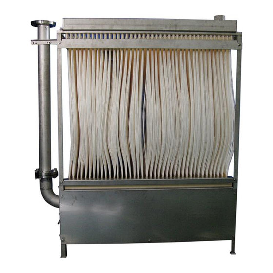
Aeration from the diffuser part cleans the hollow-fiber membranes to enable stable filtration. (See p.14 “2-2 Membrane Scour Aeration Devices”) A variety of modules are available with different element sizes and number of elements. (See p.56 “Chapter 10 Specifications”) Module(57M0200FF) Element(57E0005SM) 53/58 STERAPORE 5700 Series (FF) Instruction Manual... - Page 54 * The terms in this glossary are defined based on how they are used in this manual. These definitions and uses may differ from standard ones. For general terms related to wastewater treatment, refer to the following. Reference Gesuido Yogoshu Sewage Terms Glossary 2000 Edition (in Japanese only) Japan Sewage Works Association 54/58 STERAPORE 5700 Series (FF) Instruction Manual...
-
Page 55: List Of Consumables
○: Can be used for a short period of time such as for chemical cleaning. △: Cannot be used in principle. (Consult with us about conditions under which it may be used.) ×: Cannot be used. 55/58 STERAPORE 5700 Series (FF) Instruction Manual... -
Page 56: Chapter 10 Specifications
Silicon antifoaming agents may not be used. •d). It differs Design filtration flow is calculated based on the assumption that flux is between 0.2 and 1.0 m according to the raw water conditions, operating temperature, etc. 56/58 STERAPORE 5700 Series (FF) Instruction Manual... -
Page 57: 10-2 Module Specifications
Guide rail Filtered water hose and pipes, air None Chains and shackles hose and pipes Chain blocks and cranes Protective sheets and covers Slings and lifting beams 57/58 STERAPORE 5700 Series (FF) Instruction Manual... - Page 58 STERAPORE 5700 Series (FF) Instruction Manual 1st Edition, September 2015 ----------------------------------------For inquiries, please contact: MITSUBISHI RAYON AQUA SOLUTIONS CO., LTD. Membrane Department Membrane Division 10F Gate City Ohsaki East Tower, 1-11-2 Osaki, Shinagawa-ku, Tokyo, 141-0032, Japan TEL: 81-3-6748-7467 / FAX: 81-3-5487-7527...
Need help?
Do you have a question about the STERAPORE 5700 Series and is the answer not in the manual?
Questions and answers