Table of Contents
Advertisement
Quick Links
Designed, Manufactured and Supported in the USA
VIKING
SECURITY & COMMUNICATION
VoIP Entry Phones in 4 Attractive Finishes that
Mount in Standard Double Gang Electrical Boxes
The E-60-IP Series are compact, vandal resistant VoIP Entry Phones designed to
provide quick and reliable handsfree communication for SIP VoIP phone systems
with PoE. The E-60-IP Series entry phones can be programmed from any Touch
Tone phone, PC, or remotely using a static IP address. The Entry phones can dial up
to 5 programmable numbers. On-board 2 Amp relay contacts are provided for
activating doorstrikes or gate controllers. An optional RC-4A Secure Relay Controller
can also be used.
The E-60-IP's compact size allows it to be mounted in a standard double gang
electrical box. The E-60-IP is available in four different attractive finishes to match
your door hardware, light fixtures, etc. Replacement E-60 faceplates (PNL60) can be
purchased separately and are available in all four standard finishes. The E-60-IP's
blue LED continually provides light for locating the push button in dark locations,
flashes during dialing and automatically lights again when the call is answered. All
programming parameters, including phone numbers and location numbers, are stored
in non-volatile memory, requiring no batteries. All units are PoE powered.
The E-60-IP-EWP Series shares all the features of the E-60-IP Series in addition to
Enhanced Weather Protection (EWP) for outdoor installations where the unit is exposed
to precipitation or condensation. EWP products are designed to meet IP66 standards
and may feature foam rubber gaskets, sealed connections, gel-filled butt connectors,
as well as potted circuit boards with internally sealed, field-adjustable trim pots and DIP
switches for easy on-site programming. For more information on EWP, see DOD 859.
Installation requires the assistance of a Network Administrator / IT Technician.
!
Features
• Compact: Front panel is the size of a typical double gang mid-size wall plate
• Mounting: Flush mounts in a double gang electrical box (2.25" deep x 3.65" wide x
2.84" tall minimum) or surface mounts in an optional VE-5x5 (see DOD 424) for
mounting to a wall, post or VE-GNP Gooseneck Pedestal (EWP recommended)
• Available in 4 standard faceplate finishes: Brushed Stainless Steel, Oil Rubbed Bronze,
Textured Black and Satin White
• PNL-60 faceplates: Replacement faceplates with matching screws available in all four
standard finishes
• Self diagnostic reports via email (testing com, microphone, speaker, and switch)
• Automatic polling and programming software included
• 2 Amp relay contacts for door / gate or SL-2 strobe light control
• Blue LED indicator
• SIP compliant (see page 2 for compatible SIP servers and IP phone systems)
• Outbound Proxy, Authentication ID, Peer to Peer, VLAN Tagging
• PoE powered (class 1, <4 Watts)
• Automatic Noise Canceling (ANC) for proper operation in noisy environments
• VoIP eliminates the need for "Push to Talk" mode
• Network downloadable firmware
• Can be used with optional RC-4A Secure Relay Controller (DOD 582)
• Handsfree operation
• 304 stainless steel prevents corrosion on the stainless steel models
• Programmable to dial up to 5 numbers on busy or ring no answer
• Cycles through backup phone numbers on busy or no-answer
• Optional Enhanced Weather Protection (EWP), EWP products are designed to meet
IP66 Ingress Protection Rating, see DOD 859
• Hangs up on busy signal, time-out or touch tone command
• Remotely programmable
• Extended temperature range (-40°F to 140°F)
• Volume adjustments for microphone and speaker
• Optional PB-100 Polling System available (DOD 232)
• Optional SL-2 or BLK-4-EWP strobe light kit available (DOD 242 and 653)
PRODUCT
MANUAL
• Gate Entrance
• Parking ramps/lots
• ATM machines
• Medical centers
• Lobbies
Power: PoE class 1 (<4 Watts)
Maximum Sound Pressure: 89 dB SPL @ 1 m
Dimensions: Faceplate: 123.8 mm x 125.4 mm x 4.3 mm (4.875" x 4.938"
x 0.17"), Phone: 72 mm x 46 mm x 42 mm (2.84" x 1.8" x 1.65")
Shipping Weight: 0.55 kg (1.2 lbs)
Operating Temperature: -40°C to 60°C (-40°F to 140°F)
Humidity - Standard Products: 5% to 95% non-condensing
Humidity - EWP Products: Up to 100%
Audio Codecs: G711u, G711a, G722
Network Compliance: IEEE802.3af PoE, SIP 2.0 RFC3261, 100BASE-TX
with auto cross over
Regulatory Compliance: FCC Part 15, CE, and Canada ICES-3 Class A
Connections: (1) RJ45 10/100 Base-T, (3) gel-filled butt connectors
E-60-IP Series
Double Gang Mount
VoIP Entry Phones
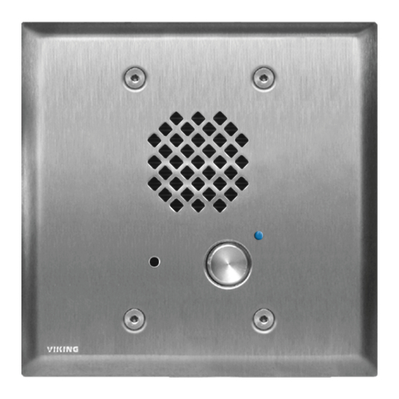
E-60-SS-IP
"Brushed Stainless Steel"
(similar to Brushed Nickel)
Shown with optional VE-5x5 surface
mount box & VE-LIGHT (not included)
E-60-WH-IP
"White"
(satin white powder paint)
Applications
• Entryways
• Stadiums
• Convention centers
• Public access areas
www.VikingElectronics.com
Information: 715-386-8861
Specifications
June 2, 2020
E-60-BN-IP
"Oil Rubbed Bronze"
(satin dark brown powder
paint with fine copper metallic)
E-60-BK-IP
"Black"
(fine texture black powder paint)
Advertisement
Table of Contents

Related Manuals for Viking E-60-IP Series


Summary of Contents for Viking E-60-IP Series
- Page 1 All units are PoE powered. The E-60-IP-EWP Series shares all the features of the E-60-IP Series in addition to Enhanced Weather Protection (EWP) for outdoor installations where the unit is exposed to precipitation or condensation.
- Page 2 VoIP SIP System Compatibility For compatibility and vendor specific detailed configuration instructions, see the Viking VoIP SIP System Compatibility List, DOD 944. To open and download this PDF file: Scan the QR code below to open 1. Go to www.vikingelectronics.com...
- Page 3 Definitions Client: A computer or device that makes use of a server. As an example, the client might request a particular file from the server. DHCP: Dynamic Host Configuration Protocol. In this procedure the network server or router takes note of a client’s MAC address and assigns an IP address to allow the client to communicate with other devices on the network.
-
Page 4: Features Overview
0.082 inches. Cut off stripped wire ends before terminating. * Note: For applications requiring additional security, a Viking model RC-4A remote relay controller can be used. The relay controller is mounted securely inside the building and connected to the same LAN as the E-60-IP. For more information on... -
Page 5: Installation
The E-60-IP is designed to be flush mounted into a standard double gang rough-in box with minimum inside dimensions of 2.25” deep x 3.65” wide x 2.84” tall. The E-60-IP can also be surface mounted using a Viking VE-5x5 for mounting to a wall, post or Viking model VE-GNP gooseneck pedestal, EWP model recommended (not included, see DOD# 424). - Page 6 D. Mounting the Faceplate After the rough-in box or VE-5x5 is securely mounted, caulking between the box and rough opening is completed (if required), and wires are connected, remove paper liner from faceplate gasket. While firmly holding the LED light pipe in the faceplate, carefully slide the faceplate gasket over the back of the light pipe and press gasket to the back of the faceplate.
- Page 7 E. Replacement IP Board Kit (Model E-1600-53A-IP) This is a board (PCB) only kit, no chassis is included. This kit can be used to convert any Viking E-60 analog phone to a VoIP version. The kit can also be used to replace a damaged IP board in the field. This kit comes in standard and EWP version.
- Page 8 2. Click E-60-SS-IP in the search results 3. Scroll down the page to Downloads, click IP Programming Software 4. Install the programming software by saving or opening the file and then clicking on setup Viking IP Programming.exe 5. Follow the prompts on your screen to complete software installation 6.
-
Page 9: Connect / Disconnect
A. Connect / Disconnect Open the “Viking IP Programming” software on the PC and the start screen shown below will appear. Any Viking IP phones that are connected to the network will appear on the list. Simply select the Entry Phone on the list and click on the “Connect”... - Page 10 C. Configuring the E-60-IP Network Settings Open the “Viking IP Programming” software on a windows PC that is connected to the same LAN as the E-60-IP phone Step 1. to be programmed. The window in the upper left corner of the menu will show you each E-60-IP phone that is connected to that LAN. Select the unit with the same MAC address shown on the label located on the top of the Ethernet connector on the E-60-IP Step 2.
- Page 11 D. Configuring E-60-IP VLAN Settings Step 1. Click on the “VLAN” tab Step 2. Disable or enable VLAN tagging by setting the value of “VLAN Tagging”. Step 3. Set the VLAN tag ID by selecting an integer (1 to 4094) in “ID for all packets”. Set the Priority Code Point (PCP) value for all not SIP and RTP packets in the “PCP for all packets”...
- Page 12 Programming Features Index DESCRIPTION Section Page Connect/Disconnect VLAN Settings Unit Name SIP Server Peer to Peer Settings Outbound Proxy Authentication ID Register Fails Speed Dial Numbers Security code (factory set to 845464) ID Number Access Code (1 - 6 digits, blank = disabled, factory set to 123456) Internal / External Relay (factory set to Internal) Relay Mode (Door Strike, Outbound Call, In / Outbound Call, Doorbell, LV-1K Control, Ring, Ring Flash, factory set to Door Strike) Relay Activation Command (1 or 2 digits, factory set to...
-
Page 13: Programming Features
Programming Features 1. Unit Name Up to a 31 character unit name can be assigned to the E-60-IP being programmed. 2. SIP Server Enter the IP address or URL of your SIP server or service provider in this field. The SIP server IP address is limited to 74 characters. -
Page 14: Security Code
Note: A majority of the features below can also be Touch Tone (In-Band DTMF) programmed. See DOD 949. 7. Speed Dial Phone Numbers Note: Up to 79 digits can be stored in each of the 5 speed dial phone number positions. The number programmed in the first location under “Speed Dial Numbers”... - Page 15 With the relay set to “Internal” the Entry Phone will activate its on board relay for door strike / gate control. The Relay should be set to “External” for higher security installations when using a Viking remote model RC-4A relay controller to activate the door strike / gate controller (see page 22).
- Page 16 16. Relay Latch Commands When set to “Enabled” the Remote Access Operation Commands (Q0 to Q1) to Un-Latch or Latch the relay are enabled. These can be entered on a Inbound call after the access code is dialed (if programmed). When set to “Disabled”...
-
Page 17: Lap Counter
25. Lap Counter With the lap counter disabled, if the Entry Phone is programmed to dial the next number on ring-no-answer and/or busy signal, the Entry Phone will continuously call its programmed phone numbers forever until the call is answered. The lap counter is a programmable counter that determines how many times the Entry Phone will cycle through its list of up to 5 Speed Dial phone numbers, before it stops the dialing process and hangs up. - Page 18 29. Dial Next Number on Ring No Answer If enabled and a ring-no-answer is detected, the Entry Phone will dial the next programmed Speed Dial number after the programmed amount of rings. A momentary press of the call button will dial the first programmed Speed Dial number. Factory Setting: 7 (will redial after 7 rings) 30.
- Page 19 “Update IP” button. You can then browse to the folder that contains the PIP file for updating the unit’s IP firmware. This method is typically only used when Viking Technical Support has sent you updated IP firmware. 37. Unit Firmware If new Entry Phone firmware is available, after opening the programming software a pop up window will ask if you would like to update firmware.
-
Page 20: Operation
Group settings and Addresses. Note: This will not effect any speaker or paging settings. 41. Diagnostics The Diagnostics section in the Viking IP Programming can be used to test the functionality of the mic, speaker and the on-board relay. Note: This will not work when relay mode is set to external or Alarm. - Page 21 When using an RC-4A for remote relay control the relays should be set to “External” in the PC programming. Note: If the Entry Phone loses communications with the RC-4A, the LED on the front panel of the E-60-IP Series will flash 3 times every 2 seconds indicating the communication error.
-
Page 22: Related Products
VE-Series enclosure to a metal surface can affect the operation of the enclosed product. For more information on Viking Surface Mount Boxes and Pedestals, see DOD 424. Add Panel Lighting to Your Viking VoIP Entry Phone The VE-LIGHT kit adds bright LED illumination to any VoIP entry phone that is housed in a Viking VE-5x5, VE-6x7 or VE-5x10 enclosure. -
Page 23: Warranty
TWO YEAR LIMITED WARRANTY Viking warrants its products to be free from defects in the workmanship or materials, under normal use and service, for a period of two years from the date of purchase from any authorized Viking distributor. If at any time during the warranty period, the product is deemed defective or malfunctions, return the product to Viking Electronics, Inc., 1531 Industrial Street, Hudson, WI., 54016.
Need help?
Do you have a question about the E-60-IP Series and is the answer not in the manual?
Questions and answers