Table of Contents
Advertisement
FOREWORD
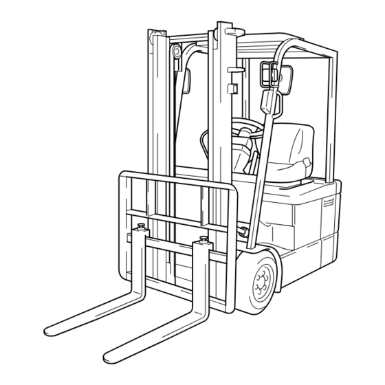
This manual covers the service procedures of the TOYOTA ELECTRIC
POWERED FORKLIFT 7FBE10 to 20 series.
Please use these manuals for providing quick, correct servicing of the corre-
sponding forklift models.
This manual deals with the above models as of February 2003. Please under-
stand that disagreement can take place between the descriptions in the man-
ual and actual vehicles due to change in design and specifications. Any
change or modifications thereafter will be informed by Toyota Industrial
Equipment Parts & Service News.
Advertisement
Table of Contents


Need help?
Do you have a question about the 7FBE10 and is the answer not in the manual?
Questions and answers