Table of Contents
Advertisement
Quick Links
Important Instructions........................................................................
Produ t Spe ifi atio s........................................................................
Unpacking & Mou ti g .....................................................................
Co
e tio T pe .............................................................................
Connection Diagram....................................................................... 6
Co
e tio T pe ........................................ ....................................
Co
e tio T pe .............................................................................
Ele tri al Data Sheet .........................................................................
Re o
________________________________________________________________________________________
Field Installation Manual
e ded Part List.....................................................................
ES-65
INDEX
1
2
3
4
5
7
8
9
10
Advertisement
Table of Contents

Summary of Contents for Celec ES-65
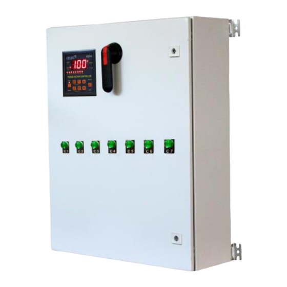
- Page 1 ES-65 Field Installation Manual INDEX Important Instructions……………………………………………………………… Produ t Spe ifi atio s…………………………………………………..…………. Unpacking & Mou ti g …………………………………………………………… e tio T pe ……………………………………………………………..…… Connection Diagram............... 6 e tio T pe ……………………………..……………………………… e tio T pe ……………………………………………………….…………. Ele tri al Data Sheet ………………………………………..……………………..
-
Page 2: Important Instructions
Any warning provided by Celec must be passed through to the end user. Celec offers a warranty only as to the quality of its product to confirm to the catalog specifications. No other warranty is offered. Celec assumes no liability for any personal injury, property damage, losses or claims arising out of the misapplication and Non performance of its products. - Page 3 ES-65 PRODUCT SPECIFICATIONS Model: ……………………………………………………………………………… ES-65 Rated Voltage……………………………………………………………………… 277/480V AC Phases………………………………………………………………………………… Three phase Wye/Delta Rated Frequency………………………………………………………………… 60Hz Maximum Current…………..………………………………………………… 79 Amp per phase Rated kVar ..……………………………………………………………………… Maximum Ambient Temperature ……….……………………………… 40 Enclosure……………………………………………………………………………… Type 1 Connection Connection Wire Type & Torque N-m...
- Page 4 CAUTION Indoor Use Only, Type-1 Enclosure. 1. Choose the dry and Clean Wall to Install the ES-65 taking care conduit connections from top side Enclosure Size is 600 x 760 x 210 mm and weight 52kg (115 pounds). 2. Premark the Mounting holes on wall or structure.
-
Page 5: Connection Type
Main Breaker Panel. 1.1 Power Connections 1.11 Switch off the external handle of load break switch (LBS), using panel key open the door of ES-65 exposing connections. 1.12 Locate Earth Terminal in ES-65 on the top, connect the earth wire to ES-65 Earth Terminal. Connect the other side of earth wire to main breaker panel ground rod. - Page 6 ________________________________________________________________________________________...
- Page 7 ES-65 units should be mounted with four appropriate sized fasteners before connect to Main Breaker Panel. 1. Switch off the external handle of load break switch (LBS), using panel key open the door of ES-65 exposing connections. 2. Remove existing 3 Pole breaker blanks and install new 3 Pole 125 Amp circuit Breakers.
- Page 8 / o duit. to ES- 3. Locate earth ground connection in ES-65 and connect to grounding bar or to earth ground rod in main breaker panel. 4. For rest of connection follow the Connection type#1 on page 5.
- Page 9 ES-65 Field Installation Manual Electrical Data Sheet Model ES-65 Phase Configuration Three Phase 277/480V AC WYE/Delta Maximum Line Voltage 480V AC Maximum Power 65 kVar Steps Monitoring PF, kVA, kVar, Volt, Current, KW, %THD-V Internal Temperature & Capacitor Status Accuracy 0.7 kVar each Phase , 2.1 Kvar three Phase...
-
Page 10: Recommended Parts List
Mai Breaker Pa el shall e the responsibility of the qualified Electrician in accordance with NEC. Any and all connections exterior to the ES-65 unit shall be the responsibility of the qualified Electrician. ________________________________________________________________________________________...


Need help?
Do you have a question about the ES-65 and is the answer not in the manual?
Questions and answers