Advertisement
Quick Links
E l ec t r if i e d Lo ck s , Re l a y s a nd Ti mers
CX-WEC10BK2
Emergency Control Kit
INSTALLATION INSTRUCTIONS
THIS PACKAGE INCLUDES:
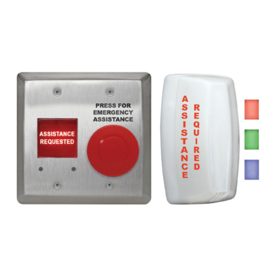
1- CM-AF540SO
1- CM-AF142SO
1. DESCRIPTION
The CX-WEC10BK2 Emergency Control Kit allows an individual to
push the "PRESS FOR EMERGENCY ASSISTANCE" button to signal
for help by illuminating the "Assistance Required" annunciator
on the outside, and the "Assistance Requested" annunciator on
the inside of the location. At the same time the sounders built
into both annunciators will activate. The kit includes signage
that states in the event of an emergency to press the button
and an audible and visual signal will activate.
The CX-WEC10BK2 kit comes with the inside activation and
annunciator built onto a double gang combination plate making
installations quicker since one back box install is needed rather
that two single gang boxes. The CM-AF142SO offers different
color options (Red, Green, Blue and White), an adjustable flash
rate and variable volume control.
Note: CX-WEC10BK2 Emergency Call System is OBC Regulation
368/13, Section 3.8.3.12 compliant.
2. OPERATION AT A GLANCE
When the "PRESS FOR EMERGENCY ASSISTANCE" button on
the CM-AF540SO is pushed in it will change its normally open
contact to a closed contact and activate the outside light and
sounder (CM-AF142S0) to signal for help. The inside lights
and sounder (CM-AF540SO) will also be activated giving the
individual inside confirmation that the action has taken place.
Once the emergency has been attended to the red mushroom
button on the CM-AF540SO can be pulled out to silence and
reset the system. The flash rate can be adjusted at the top right
of the circuit board after removing the front dome cover. The
volume can be increased or decreased by using the adjustment
screw on the back of the CM-AF142SO.
Power
Both the CM-AF540SO and the CM-AF142SO can be powered
with either 12/24 VAC/VDC.
Note: When the CX-WEC10BK2 is integrated with a Camden
Restroom Control Kit, VDC power must be used to prevent
the door strike from buzzing.
Wiring the CX-WEC10BK2 Emergency Control Kit
The inside and outside annunciators are wired in parallel to
make them work at the same time when triggered.
1- CM-SE21A
Take one of the black wires from the CM-AF540SO and the black
wire from the CM-AF142SO and tie them to the power supply's
VDC ground (-). Take the remaining black wire from the
CM-AF540SO and one of the Red, Blue or Green wires from the
CM-AF142SO (or take all colored wires from the CM-AF142SO to
make White) and wire it to the red mushroom buttons, normally
open contact marked with as terminal "3". Next, wire the
terminal marked as "4" to the positive (+) terminal of the
VDC power supply.
Note: Some Door Operators provide excessive voltage levels
above their posted values. Always measure voltages provided
on both the VDC & VAC scales first before applying power to
any part of the Emergency Control Kit.
3. INSTALLATION
CM-AF540SO
Supplied with a stainless steel
faceplate that can be easily
mounted to a double gang
electrical box.
P R
E S
E M
S F
E R
O R
A S
G E
S I S
N C
T A
N C
Volume Adjust
Turn the volume adjust
clockwise to increase the
volume and counter
clockwise to decrease the
volume. Turn the volume
adjust all the way counter
clockwise to turn the
sounder completely off.
Y
E
Volume
Adjust
1
3
4
2
Page 1 of 4
Advertisement

Related Manuals for CAMDEN CX-WEC Series


Summary of Contents for CAMDEN CX-WEC Series
- Page 1 Adjust with either 12/24 VAC/VDC. clockwise to increase the volume and counter Note: When the CX-WEC10BK2 is integrated with a Camden clockwise to decrease the Restroom Control Kit, VDC power must be used to prevent the door strike from buzzing.
- Page 2 CX-WEC10BK2 Emergency Door Control Kit INSTA L L AT I O N I NST RU CTI ONS CM-AF142SO Mounts to a standard single gang electrical box. Step 1 Step 2 Place the gasket (supplied) between the base unit and the Insert the O ring gasket into the small channel in front of the base.
- Page 3 CX-WEC10BK2 Emergency Door Control Kit INSTA L L AT I O N I NST RU CTI ONS 4. DOUBLE GANG CM-AF540SO MOUNTING Wall CM-AF540SO 5502 Timberlea Blvd. Mississauga, ON Canada L4W 2T7 Tel: (905) 366-3377 www.camdencontrols.com CM-AF540SO Double Gang Flush Mount A.OLISA MAR-20 5.
- Page 4 CX-WEC10BK2 Emergency Door Control Kit INSTAL L AT ION INS T RUCT IONS ORDERING INFORMATION FOR REPLACEMENT PARTS Item Part Number Description CM-SE21A English Solid white WEC Sign 6’’ x 10-5/8’’ CM-AF142SO 60-31A081 Red Green Blue LED PCB Board 18-30 VAC/VDC 60-42K003 Single Gang Dress Plate 60-42C027-A...