Advertisement
SPLIT-TYPE, HEAT PUMP AIR CONDITIONERS
TECHNICAL & SERVICE MANUAL
Indoor unit
[Model Name]
TPMFYP006BM140F
TPMFYP008BM140F
TPMFYP012BM140F
TPMFYP015BM140F
Grille model
[Model Name]
TMP-16BMUW
INDOOR UNIT
No. OCHT341
R410A
CONTENTS
1. FEATURES ...........................................2
2. PART NAMES AND FUNCTIONS ........2
3. SPECIFICATION ...................................9
4. OUTLINES AND DIMENSIONS .........13
5. WIRING DIAGRAM .............................14
7. MICROPROCESSOR CONTROL ...... 16
8. TROUBLESHOOTING .........................23
9. DISASSEMBLY PROCEDURE ............31
SERVICE MANUAL (OCBT341)
April 2019
Advertisement
Table of Contents

Subscribe to Our Youtube Channel
Related Manuals for Mitsubishi Electric TRANE CITY MULTI TPMFYP006BM140F


Summary of Contents for Mitsubishi Electric TRANE CITY MULTI TPMFYP006BM140F
-
Page 1: Table Of Contents
SPLIT-TYPE, HEAT PUMP AIR CONDITIONERS April 2019 No. OCHT341 TECHNICAL & SERVICE MANUAL R410A Indoor unit [Model Name] TPMFYP006BM140F TPMFYP008BM140F TPMFYP012BM140F TPMFYP015BM140F Grille model [Model Name] TMP-16BMUW CONTENTS 1. FEATURES ...........2 2. PART NAMES AND FUNCTIONS ..2 3. SPECIFICATION ........9 4. -
Page 2: Features
Use the specified refrigerant only Never use any refrigerant other than that specified. Doing so may cause a burst, an explosion, or fire when the unit is being used, serviced, or disposed of. Correct refrigerant is specified in the manuals and on the spec labels provided with our products. We will not be held responsible for mechanical failure, system malfunction, unit breakdown or accidents caused by failure to follow the instructions. - Page 3 2-2. Wired Remote Controller <TAR-40MAA> Controller interface The functions of the function buttons change depending on the screen. Refer to the button function guide that appears at the bottom of the LCD for the functions they serve on a given screen. When the system is centrally controlled, the button function guide that corresponds to the locked button will not appear.
- Page 4 Display The main display can be displayed in two different modes: “Full” and “Basic”. The initial setting is “Full”. To switch to the “Basic” mode, change the setting on the Main display setting. (Refer to operation manual included with remote controller.) <Full mode>...
- Page 5 Main menu Press the button. MENU Move the cursor to the desired item with the buttons, and press the button. SELECT Operation Vane · Louver · Vent. (Lossnay) High power Comfort Manual vane angle 3D i-see Sensor Timer menu Timer ON/OFF timer Auto-OFF timer Weekly timer...
- Page 6 Continue from the previous page. Maintenance menu Error information Filter information Cleaning Auto descending panel Descending operation Descending adjustment Service menu Test run menu Test run Drain pump test run Maintenance information Model name input Serial No. input Dealer information input Initialize maintenance info.
- Page 7 Main menu list Main Setting and display items Setting details menu Operation Vane · Louver · Vent. Use to set the vane angle. (Lossnay) • Select a desired vane setting from 5 different settings. Use to turn ON/OFF the louver. •...
- Page 8 Main Setting and display items Setting details menu Initial Basic Main/Sub When connecting 2 remote controllers, one of them needs to be designated as setting setting a sub controller. Clock Use to set the current time. Daylight Set the daylight saving time. saving time Administrator The administrator password is required to make the settings for the following...
-
Page 9: Specification
SPECIFICATION 3-1. SPECIFICATIONS Service ref. TPMFYP006BM140F TPMFYP008BM140F TPMFYP012BM140F TPMFYP015BM140F Item Power V · H Single phase 208-230V 60Hz Cooling capacity Btu/h 6,000 8,000 12,000 15,000 Heating capacity Btu/h 6,700 9,000 13,500 17,000 Cooling 0.04 0.04 0.04 0.05 Input Heating 0.04 0.04 0.04 0.05... - Page 10 3-2. ELECTRICAL PARTS SPECIFICATIONS Service Ref. Symbol TPMFYP006BM140F TPMFYP008BM140F TPMFYP012BM140F TPMFYP015BM140F Parts name Room temperature Resistance 30°F/15.8kΩ, 50°F/9.6kΩ, 70°F/6.0kΩ, TH21 thermistor 80°F/4.8kΩ, 90°F/3.9kΩ, 100°F/3.2kΩ Resistance 30°F/15.8kΩ, 50°F/9.6kΩ, 70°F/6.0kΩ, Liquid pipe thermistor TH22 80°F/4.8kΩ, 90°F/3.9kΩ, 100°F/3.2kΩ Resistance 30°F/15.8kΩ, 50°F/9.6kΩ, 70°F/6.0kΩ, Gas pipe thermistor TH23 80°F/4.8kΩ, 90°F/3.9kΩ, 100°F/3.2kΩ...
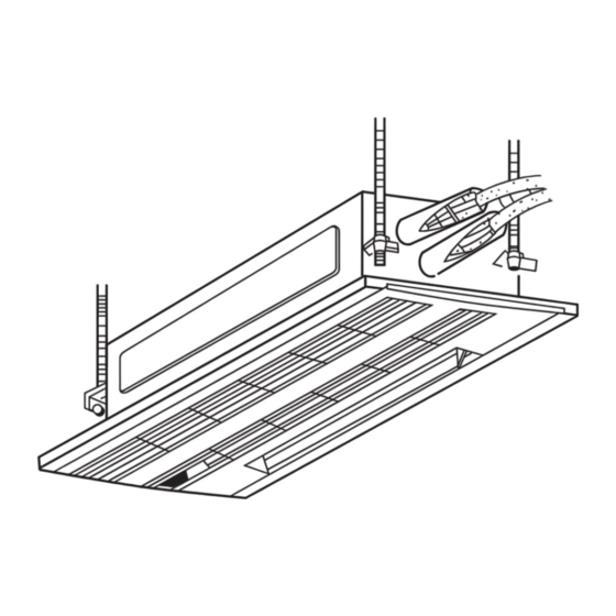
- Page 11 3-3. AIR CAPACITY TAKEN FROM OUTSIDE TPMFY series are capable of taking air from outside. When taking air from outside, the duct fan is used. The air capacity should be 20% or less of the airflow SPEC (Hi). 9-13/16 11-3/8 4-Ø1/8 Fresh air intake hole Fresh air intake hole...
- Page 12 3-4. NOISE CRITERION CURVES TPMFYP006BM140F TPMFYP008BM140F SPL(dB) LINE NOTCH SPL(dB) LINE NOTCH High TPMFYP012BM140F High Medium1 Medium1 Medium2 Medium2 NC-70 NC-70 NC-60 NC-60 NC-50 NC-50 NC-40 NC-40 NC-30 NC-30 APPROXIMATE THRESHOLD OF NC-20 HEARING FOR NC-20 CONTINUOUS APPROXIMATE THRESHOLD OF HEARING NOISE FOR CONTINUOUS NOISE 1000...
-
Page 13: Outlines And Dimensions
OUTLINES AND DIMENSIONS TPMFYP006BM140F Unit : inch (mm) TPMFYP008BM140F TPMFYP012BM140F TPMFYP015BM140F OCHT341... -
Page 14: Wiring Diagram
WIRING DIAGRAM TPMFYP006BM140F TPMFYP008BM140F TPMFYP012BM140F TPMFYP015BM140F OCHT341... -
Page 15: Refrigerant System Diagram
REFRIGERANT SYSTEM DIAGRAM TPMFYP006BM140F TPMFYP008BM140F TPMFYP012BM140F TPMFYP015BM140F Refrigerant flow in cooling Refrigerant flow in heating Thermistor TH23 Strainer (#100mesh) <Gas pipe temperature detection> Gas pipe Thermistor TH22 <Liquid pipe temperature detection> Flare connection Liquid pipe Heat exchanger Linear expansion valve Strainer (#50mesh) Strainer... -
Page 16: Microprocessor Control
MICROPROCESSOR CONTROL INDOOR UNIT CONTROL 7-1. COOL OPERATION <How to operate> 1 Press ON/OFF button. 2 Press [F1] button to display COOL. 3 Press [F2] [F3] button to set the set temperature. NOTE: The settable temperature range varies with the model of outdoor units and remote controller. RETURN SELECT MENU HOLD... - Page 17 Control modes Remarks Control details 3. Drain pump 3-1. Drain pump control • The drain pump will always run when the unit is in COOL or DRY mode. (Regardless of the thermostat ON/OFF) • When the operation mode is changed from COOL or DRY to any other mode (including Stop), the drain pump continues to run for 3 minutes.
- Page 18 7-2. DRY OPERATION <How to operate> 1 Press ON/OFF button. 2 Press [F1] button to display DRY. 3 Press [F2] [F3] button to set the set temperature. RETURN SELECT MENU HOLD <How to operate> 1 Press POWER ON/OFF button. 2 Press the operation MODE button to display DRY. 3 Press the TEMP.
- Page 19 7-3. FAN OPERATION <How to operate> 1 Press ON/OFF button. 2 Press [F1] button to display FAN. RETURN SELECT MENU HOLD <How to operate> 1 Press POWER ON/OFF button. 2 Press the operation MODE button to display FAN. Control modes Control details Set by remote controller. 1.
- Page 20 7-4. HEAT OPERATION <How to operate> 1 Press ON/OFF button. 2 Press [F1] button to display HEAT. 3 Press [F2] [F3] button to set the set temperature. NOTE: The settable temperature range varies with the model of outdoor units and remote controller. RETURN SELECT MENU HOLD <How to operate>...
- Page 21 From the preceding page. Control modes Control details Remarks This control is 2. Fan 2-2. Residual heat exclusion mode same for the When the condition changes the auxiliary heater ON to OFF model without (thermostat or operation stop, etc), the indoor fan operates in [Low] mode for auxiliary heater.
- Page 22 7-5. AUTO OPERATION [AUTOMATIC COOL/HEAT CHANGE OVER OPERATION] <How to operate> 1 Press ON/OFF button. 2 Press [F1] button to display AUTO. 3 Press [F2] [F3] button to set the set temperature. NOTE: The settable temperature range varies with the model of outdoor units and remote controller. RETURN SELECT MENU HOLD...
-
Page 23: Troubleshooting
TROUBLESHOOTING 8-1. HOW TO CHECK THE PARTS TPMFYP006BM140F TPMFYP008BM140F TPMFYP012BM140F TPMFYP015BM140F Parts name Checkpoints Thermistor (TH21) Disconnect the connector then measure the resistance with a tester. <Room temperature (At the ambient temperature 50˚F~86˚F) detection> Thermistor (TH22) Normal Abnormal Refer to the next page for the details. <Liquid pipe temperature 4.3k"... - Page 24 < Thermistor for lower temperature > <Thermistor characteristic graph> Thermistor for Thermistor <Room temperature detection> (TH21) lower temperature Thermistor <Liquid pipe temperature detection> (TH22) Thermistor <Gas pipe temperature detection> (TH23) Thermistor R =15k' ± 3% Fixed number of B=3480 ± 2% Rt=15exp { 3480( 273+(t-32)/1.8 30_F...
- Page 25 <Output pulse signal and the valve operation> Output Output The output pulse shifts in below order. (Phase) Closing a valve : 1 → 2 → 3 → 4 → 1 ø1 Opening a valve : 4 → 3 → 2 → 1 → 4 ø2 ø3 •...
- Page 26 8-2. FAN MOTOR CHECK Check method of indoor fan motor (fan motor/controller board) Notes · High voltage is applied to the connector (CNMF1, 2) for the fan motor. Pay attention to the service. · Do not pull out the connector (CNMF1, 2) for the motor with the power supply on, doing so may result in damage to the board.
- Page 27 8-3. FUNCTION OF DIP SWITCH Operation by switch Effective Switch Pole Function Remarks timing Thermistor <Room temperature Built-in remote controller Indoor unit Address board detection> position Filter clogging detection Provided Not provided <Initial setting> Filter cleaning sign 2,500h 100h Fresh air intake Effective Not effective 1 2 3 4 5 6 7 8 9 10...
- Page 28 Effective Switch Pole Operation by switch Remarks timing SW11 Address board 1s digit How to set addresses address SW12 SW11 <Initial setting> Example: If address is “3”, remain SW12 setting SW12 SW11 (for over 10) at “0”, and match SW11 (for 1 to 9) SW12 with “3”.
- Page 29 8-4. TEST POINT DIAGRAM 8-4-1. Indoor controller board TPMFYP006BM140F TPMFYP008BM140F TPMFYP012BM140F TPMFYP015BM140F Power supply Drain pump output (DP) 1-2 : 208-230V AC 1-3 : 208-230V AC FUSE 6.3A 250V CNMF1, CNMF2 FAN motor CNMF11-CNMF21 : 294-325V DC CNMF23-1 : 15V DC CNMF25-1 : 0-6.5V DC CNMF27-1 : 0-15V DC LED1...
- Page 30 8-4-2. Address board TPMFYP006BM140F TPMFYP008BM140F TPMFYP012BM140F TPMFYP015BM140F Voltage selector Function setting SW12 SW11 SW14 Address setting Address setting Branch No. 10s DIGIT 1s DIGIT OCHT341...
-
Page 31: Disassembly Procedure
DISASSEMBLY PROCEDURE TPMFYP006BM140F TPMFYP008BM140F TPMFYP012BM140F TPMFYP015BM140F : Indicates the visible parts in the photos/figures. Be careful when removing heavy parts. OPERATING PROCEDURE PHOTOS/FIGURES Photo 1 Air intake grille 1. Removing the grille Opening the air intake grille Air outlet (1) Press the of the air intake grille. - Page 32 OPERATING PROCEDURE PHOTOS/FIGURES Figure 6 Removing the grille Hooks (1) Open the intake grille by pressing of the air intake PUSH grille and remove the air filter (× 2). (See Figure 1) (2) Remove the screw cover in the middle of the air outlet. (See Figure 7) (3) Open the upper and lower flaps on the indoor unit com- pletely.
- Page 33 OPERATING PROCEDURE PHOTOS/FIGURES Photo 2 Claw in middle 2. Removing the electrical parts box Nozzle Electrical parts of nozzle (1) Remove the panel. (2) Remove the address board cover. (3) Remove the electrical parts cover. (4) Disconnect the connectors of fan motor, vane motor, drain pump, room temperature thermistor, pipe temperature thermistor (Liquid.
- Page 34 OPERATING PROCEDURE PHOTOS/FIGURES Photo 6 5. Removing the drain pump (1) Remove the panel. (2) Unhook the claw in the middle of nozzle and remove the Drain sensor drain pan. (See Photo 2) (3) Remove the address board cover. (See Photo 3) Drain pump (4) Remove the electrical parts cover.
- Page 35 OCHT341...
- Page 36 MITSUBISHI ELECTRIC TRANE HVAC US LLC HEAD OFFICE: 1340 SATELLITE BOULEVARD, SUWANEE, GA 30024, USA CCopyright 2019 MITSUBISHI ELECTRIC CORPORATION Published: Apr. 2019 No.OCHT341 Made in Japan Specifications are subject to change without notice.
Need help?
Do you have a question about the TRANE CITY MULTI TPMFYP006BM140F and is the answer not in the manual?
Questions and answers