
Related Manuals for Fuji Electric P633C Series


Summary of Contents for Fuji Electric P633C Series
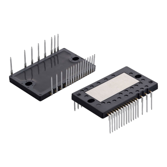
- Page 1 Small IPM (Intelligent Power Module) P633C, P633A Series 6MBP**XS*06*-50 Mounting Instruction September 2023 MT6M15589d...
- Page 2 Fuji Electric Co., Ltd. If you have any question about any portion of this application note, ask Fuji Electric Co., Ltd. or its sales agencies. Neither Fuji Electric Co., Ltd. nor its agencies shall be liable for any injury or damage caused by any use of the products not in accordance with instructions set forth herein.
-
Page 3: Table Of Contents
1. Selection 2. Shape 3. Mounting (tightening) Chapter 7 Soldering to Printed Circuit Board Chapter 8 Appendix 1. Stencil mask drawing for thermal grease application (recommended) 2. Isolation distance of heat sink MT6M15589d © Fuji Electric Co., Ltd. All rights reserved. -
Page 4: Chapter 1 Precautions During Transportation And Storage
• This product should be stored in antistatic containers or antistatic shipping bags. • Under the above storage condition, use this product within one year. MT6M15589d © Fuji Electric Co., Ltd. All rights reserved. -
Page 5: Chapter 2 Precautions In Unpacking
Fig. 2-2. (See Fig. 2-3) Removal part Fig. 2-2 Example of remover (removal jig) Fig. 2-3 Gap between the pin and the tube MT6M15589d © Fuji Electric Co., Ltd. All rights reserved. -
Page 6: Removing The Product From The Tube
• When removing the product, do not strongly collide the products with each other or bump the product terminals against the tube. A strong impact on the product may cause deforming or damage to the product terminals. MT6M15589d © Fuji Electric Co., Ltd. All rights reserved. -
Page 7: Chapter 3 Through-Hole Design For Pcb
Land Fig. 3-1 Control side Through-hole dimensions Fig. 3-2 Power side Through-hole dimensions Fig. 3-3 Through-hole layout with standard Fig. 3-4 Through-hole layout with terminals and short terminals zigzag pattern terminal MT6M15589d © Fuji Electric Co., Ltd. All rights reserved. -
Page 8: Chapter 4 Spacer
• Select a spacer material that does not cause contamination or corrosion. Recommended spacer position Spacer Side view (short side) Side view (long side) Side view of proposed spacer Fig. 4-1 Spacer position MT6M15589d © Fuji Electric Co., Ltd. All rights reserved. -
Page 9: Chapter 5 Application Of Thermal Grease
Thermal conductivity W/m・K 0.90 μm Thermal grease thickness 100±30 Thermal grease (apply to product’s aluminum base) Stencil mask Stencil mask Squeegee fixing tool (for applying thermal grease) Fig. 5-1 Thermal grease application MT6M15589d © Fuji Electric Co., Ltd. All rights reserved. -
Page 10: Chapter 6 Heat Sink Selection
• For more detailed design, please refer to IGBT Module Application Manual (REH984) and Small IPM Application Manual. ・ P633A Application Manual: MT6M08855 ・ P633C Application Manual: MT6M16945 Fig. 6-1 Temperature sensing and T measurement points MT6M15589d © Fuji Electric Co., Ltd. All rights reserved. -
Page 11: Shape
Recommended: 1 2 Pre-screwing: 2 1 Final screwing: Note: the pre-screwing torque is set to 30% of the final screwing torque rating(0.59~0.98N・m). Fig. 6-3 Recommended screw fastening order MT6M15589d © Fuji Electric Co., Ltd. All rights reserved. -
Page 12: Chapter 7 Soldering To Printed Circuit Board
• It is not recommended to reuse the product after it is removed from the printed circuit board because there is a possibility that the removed product was subjected to thermal or mechanical damage during the removal process. MT6M15589d © Fuji Electric Co., Ltd. All rights reserved. -
Page 13: Chapter 8 Appendix
: Aluminum base centerline Metal mask thickness : T = 200 μm (Target grease thickness: T = approx. 100 μm ) Fig. 8-1 Stencil mask drawing for thermal grease application (recommended) MT6M15589d © Fuji Electric Co., Ltd. All rights reserved. -
Page 14: Isolation Distance Of Heat Sink
INV. side lead Ctrl. side lead 7.7mm 3.5mm (min.) (min.) Small IPM Heat-sink Heat-sink Secure a creepage distance and clearance of 5.08 mm or more Fig. 8-2 Isolation distance of heat sink MT6M15589d © Fuji Electric Co., Ltd. All rights reserved.
Need help?
Do you have a question about the P633C Series and is the answer not in the manual?
Questions and answers