Table of Contents
Advertisement
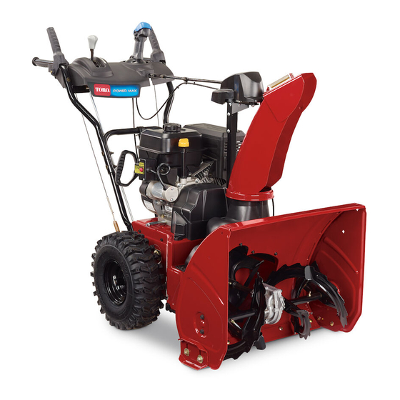
Power Max
Model No. 37798—Serial No. 409130000 and Up
Model No. 37799—Serial No. 409230000 and Up
Introduction
This machine is intended to be used by residential
homeowners. It is designed primarily for removing
snow from paved surfaces, such as driveways and
sidewalks, and other surfaces for traffic on residential
or commercial properties. It is not designed for
removing materials other than snow. Using this
product for purposes other than its intended use could
prove dangerous to you and bystanders.
Read this information carefully to learn how to operate
and maintain your product properly and to avoid
injury and product damage. You are responsible for
operating the product properly and safely.
Visit
www.Toro.com
for product safety and operation
training materials, accessory information, help finding
a dealer, or to register your product.
Whenever you need service, genuine Toro parts, or
additional information, contact an Authorized Service
Dealer or Toro Customer Service and have the model
and serial numbers of your product ready.
identifies the location of the model and serial numbers
on the product. Write the numbers in the space
provided.
Important:
With your mobile device, you can
scan the QR code on the serial number decal (if
equipped) to access warranty, parts, and other
product information.
1. Model and serial number location
© 2021—The Toro® Company
8111 Lyndale Avenue South
Bloomington, MN 55420
®
824 OE and 826 OAE Snowthrower
Figure 1
Figure 1
Register at www.Toro.com.
Model No.
Serial No.
This manual identifies potential hazards and has
safety messages identified by the safety-alert symbol
(Figure
2), which signals a hazard that may cause
serious injury or death if you do not follow the
recommended precautions.
This manual uses 2 words to highlight information.
Important calls attention to special mechanical
information and Note emphasizes general information
worthy of special attention.
Important:
If you are using this machine above
1500 m (5,000 ft) for a continuous period, ensure
that the High Altitude Kit has been installed
so that the engine meets CARB/EPA emission
regulations. The High Altitude Kit increases
engine performance while preventing spark-plug
fouling, hard starting, and increased emissions.
Once you have installed the kit, attach the
high-altitude label next to the serial decal on the
machine. Contact any Authorized Toro Service
Dealer to obtain the proper High Altitude Kit and
high-altitude label for your machine. To locate
a dealer convenient to you, access our website
at
www.Toro.com
Care Department at the number(s) listed in your
Emission Control Warranty Statement. Remove
the kit from the engine and restore the engine to
its original factory configuration when running the
g293068
engine under 1500 m (5,000 ft). Do not operate an
engine that has been converted for high-altitude
use at lower altitudes; otherwise, you could
overheat and damage the engine.
If you are unsure whether or not your machine has
been converted for high-altitude use, look for the
following label
Original Instructions (EN)
Form No. 3447-767 Rev A
Operator's Manual
Figure 2
Safety-alert symbol
or contact our Toro Customer
(Figure
3).
*3447-767*
Printed in Mexico
All Rights Reserved
g000502
Advertisement
Table of Contents

Related Manuals for Toro Power Max 824 OAE


Summary of Contents for Toro Power Max 824 OAE
-
Page 1: Introduction
Important calls attention to special mechanical additional information, contact an Authorized Service information and Note emphasizes general information Dealer or Toro Customer Service and have the model worthy of special attention. and serial numbers of your product ready. Figure 1... -
Page 2: Table Of Contents
Contents Introduction ............... 1 Safety ............... 3 General Safety ........... 3 Safety and Instructional Decals ......4 decal127-9363 Setup ................ 6 Figure 3 1 Installing the Chute .......... 6 2 Installing the Upper Handle ......6 3 Installing the Traction-Control Linkage ..... 7 4 Installing the Chute-Control Rod ...... -
Page 3: Safety
Storing the Machine.......... 26 Removing the Machine from Storage ....27 Troubleshooting ............28 Safety This machine has been designed in accordance with ANSI/OPEI B71.3 specifications. General Safety This product is capable of amputating hands and feet and of throwing objects. Always follow all safety instructions to avoid serious personal injury. -
Page 4: Safety And Instructional Decals
Safety and Instructional Decals Safety decals and instructions are easily visible to the operator and are located near any area of potential danger. Replace any decal that is damaged or missing. Order Part No. 138-8487 120-9805 decal120-9805 120-9805 1. Insert the key. 2. - Page 5 decal137-6198 137-6198 1. Cutting/dismemberment 2. Warning—shut off the hazard of the fingers or engine before using the hand, impeller—do not tool to clear the chute. place your hand in the chute. Order Part No. 138-8487 decal121-1240 121-1240 1. Traction drive—squeeze the lever to engage; release the 4.
-
Page 6: Setup
Setup Installing the Chute No Parts Required Procedure g360853... -
Page 7: Installing The Upper Handle
Installing the Upper Handle No Parts Required Procedure g263892 Installing the Traction-Control Linkage No Parts Required Procedure g252391... -
Page 8: Installing The Chute-Control Rod
Installing the Chute-Control Rod No Parts Required Procedure g257848... -
Page 9: Installing The Snow-Cleanout Tool
Installing the Snow-Cleanout Tool No Parts Required Procedure g252394 Checking the Engine-Oil Level No Parts Required Procedure Note: Your machine comes with oil in the engine crankcase. Before starting the engine, check the oil level and add oil if necessary. Refer to Checking the Engine-Oil Level (page 20). -
Page 10: Checking The Tire Pressure
Checking the Tire Pressure No Parts Required Procedure g252396 Checking the Skids and Checking the Operation of Scraper the Traction Drive No Parts Required No Parts Required Procedure Procedure Refer to Checking and Adjusting the Skids and CAUTION Scraper (page 20). -
Page 11: Product Overview
Product Overview g001011 Figure 10 The machine should move rearward. If the machine does not move or moves forward, complete the following: Release the traction lever and shut off the engine. Disconnect the trunnion from the speed-selector lever. Turn the trunnion downward (clockwise) on the speed-control rod. -
Page 12: Specifications
To ensure optimum performance and continued safety • Store fuel in an approved fuel container, out of the certification of the machine, use only genuine Toro reach of children. replacement parts and accessories. Replacement • parts and accessories made by other manufacturers... -
Page 13: Filling The Fuel Tank
Filling the Fuel Tank During Operation • For best results, use only clean, fresh (less than During Operation Safety 30 days old), unleaded gasoline with an octane rating of 87 or higher ((R+M)/2 rating method). • Oxygenated fuel with up to 10% ethanol or 15% General Safety MTBE by volume is acceptable. -
Page 14: Starting The Engine
when making any repairs, adjustments, or inspections. • Never operate the machine at high transport speeds on slippery surfaces. Starting the Engine Electric-Start Model Note: To use the electric starter (electric-start models only), connect a power cord to the plug-in first and then to a power outlet. -
Page 15: Shutting Off The Engine
Standard Model g254928 Figure 16 Shutting Off the Engine g252411 Figure 17 Operating the Traction To engage the traction drive, squeeze the left (traction) lever to the handgrip (Figure 18). Drive CAUTION If the traction drive is not properly adjusted, the machine may move in the direction opposite of what you intended, causing injury and/or property damage. -
Page 16: Operating The Speed Selector
Operating the Speed WARNING Selector If the auger and impeller continue to rotate when you release the The speed selector has 6 forward and 2 reverse auger/impeller lever, you could seriously gears. To change speeds, release the traction lever injure yourself or others. and shift the speed-selector lever to the desired Do not operate the machine. -
Page 17: Clearing A Clogged Discharge Chute
Clearing a Clogged • If the chute does not move, refer to Adjusting the Discharge-Chute Latch (page 25). Discharge Chute • If the chute does not turn as far to the left as it does to the right, ensure that the cable is routed to the inside of the handles. -
Page 18: Operating Tips
Operating Tips After Operation DANGER After Operation Safety When the machine is in operation, the impeller and auger rotate and can injure or amputate General Safety hands or feet. • Never store the machine with fuel in the fuel • Before adjusting, cleaning, inspecting, tank inside a building where ignition sources are troubleshooting, or repairing the machine, present, such as hot water heaters, space heaters,... -
Page 19: Maintenance
• Check all fasteners at frequent intervals for proper tightness to ensure that the machine is in safe working condition. • Do not change the governor settings on the engine. Purchase only genuine Toro replacement parts and accessories. -
Page 20: Checking The Engine-Oil Level
Checking the Engine-Oil Level Service Interval: Before each use or daily—Check the engine-oil level and add oil if necessary. g252395 Checking and Adjusting the Skids and Scraper Service Interval: Yearly—Check the skids and the scraper and adjust them if necessary. Check the skids and the scraper to ensure that the auger does not contact the paved or gravel surface. -
Page 21: Checking And Adjusting The Traction Cable
pavement, then adjust the skids down to the pavement. Note: If the skids become excessively worn, you can turn them over and set the unused side toward the pavement. Checking and Adjusting the Traction Cable Service Interval: After the first 2 hours—Inspect the traction cable and adjust it if necessary. -
Page 22: Checking And Adjusting The Auger/Impeller Cable
Checking and Adjusting the Checking the Auger/Impeller Cable Auger-Gearbox-Oil Level Service Interval: After the first 2 hours—Inspect the Service Interval: Yearly—Check the auger-gearbox auger/impeller cable and adjust it if oil and add oil if necessary. necessary. Move the machine to a level surface. Yearly—Inspect the auger/impeller cable and Clean the area around the pipe plug (Figure... -
Page 23: Changing The Engine Oil
Changing the Engine Oil Service Interval: After the first 5 hours—Change the engine oil. Yearly—Change the engine oil. If possible, run the engine for a few minutes before changing the oil because warm oil flows better and carries more contaminants. Engine oil capacity 0.70 L (24 fl oz)* Oil viscosity... -
Page 24: Replacing The Spark Plug
Replacing the spark plug while the engine is hot can result in burns. Wait until the engine is cool to replace the spark plug. Use a Toro spark plug or equivalent (Champion® g019018 Figure 33 RN9YC or NGK BPR6ES). 1. Hex shaft 3. -
Page 25: Adjusting The Discharge-Chute Latch
Replacing the Drive Belts If the auger/impeller drive belt or the traction-drive belt becomes worn, oil-soaked, or otherwise damaged, have an Authorized Service Dealer replace the belt. g001029 Figure 37 1. 0.76 mm (0.030 inch) Install the new spark plug, tighten it firmly, and attach the ignition wire to the spark plug. -
Page 26: Replacing The Headlight
Replacing the Headlight Model 37799 only Replace the headlight assembly (Toro part number 138-0670) when needed. Remove the headlight wire from the back of the headlight (A of Figure 39). Remove the bolt and nut holding the headlight assembly onto the headlight bracket and then remove the... - Page 27 Tighten all loose screws, bolts, and locknuts. Repair or replace any damaged parts. Cover the machine and store it in a clean, dry place out of the reach of children. Removing the Machine from Storage Perform the annual maintenance procedures as given in the Recommended Maintenance Schedule;...
- Page 28 Troubleshooting Problem Possible Cause Corrective Action The electric starter does not turn 1. The power cord is disconnected at the 1. Connect the power cord to the outlet (electric-start models only). outlet or the machine. and/or the machine. 2. The power cord is worn, corroded, or 2.
- Page 29 6. The auger/impeller drive belt is loose 6. Install and/or adjust the auger/impeller or is off the pulley. drive belt; refer to www.Toro.com for servicing information or take the machine to an Authorized Service Dealer. 7. The auger/impeller drive belt is worn 7.
- Page 30 Notes:...
- Page 31 While the exposure from Toro products may be negligible or well within the “no significant risk” range, out of an abundance of caution, Toro has elected to provide the Prop 65 warnings. Moreover, if Toro does not provide these warnings, it could be sued by the State of California or by private parties seeking to enforce Prop 65 and subject to substantial penalties.
Need help?
Do you have a question about the Power Max 824 OAE and is the answer not in the manual?
Questions and answers