Table of Contents
Advertisement
Quick Links
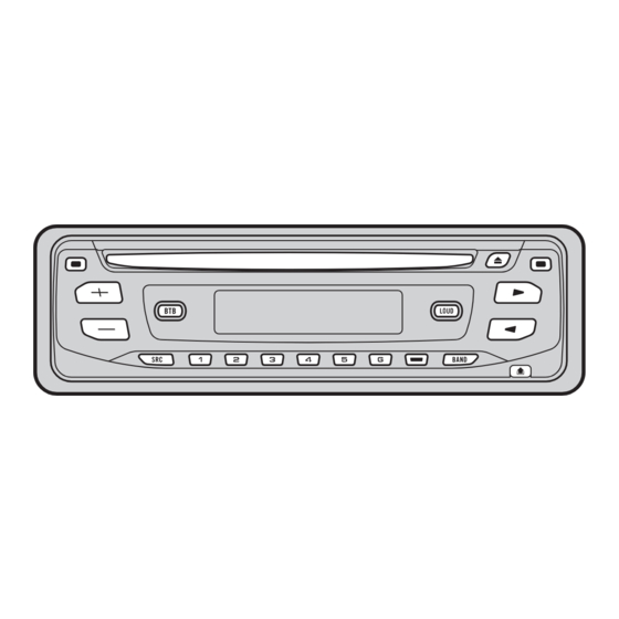
HIGH POWER CD PLAYER WITH FM/AM TUNER
DEH-1750
DEH-1770
This service manual should be used together with the following manual(s):
Model No.
Order No.
CX-3110
CRT3178
For details, refer to "Important Check Points for Good Servicing".
PIONEER CORPORATION
PIONEER ELECTRONICS (USA) INC. P.O. Box 1760, Long Beach, CA 90801-1760, U.S.A.
PIONEER EUROPE NV Haven 1087, Keetberglaan 1, 9120 Melsele, Belgium
PIONEER ELECTRONICS ASIACENTRE PTE. LTD. 253 Alexandra Road, #04-01, Singapore 159936
PIONEER CORPORATION 2004
/XN/CS
Mech.Module
S10.1
CD Mech. Module:Circuit Description, Mech. Description, Disassembly
4-1, Meguro 1-chome, Meguro-ku, Tokyo 153-8654, Japan
DEH-1750/XN/GS
/XN/GS
Remarks
ORDER NO.
CRT3377
K-ZZW. OCT. 2004 printed in Japan
Advertisement
Table of Contents

Related Manuals for Pioneer DEH-1780


Summary of Contents for Pioneer DEH-1780
- Page 1 PIONEER CORPORATION 4-1, Meguro 1-chome, Meguro-ku, Tokyo 153-8654, Japan PIONEER ELECTRONICS (USA) INC. P.O. Box 1760, Long Beach, CA 90801-1760, U.S.A. PIONEER EUROPE NV Haven 1087, Keetberglaan 1, 9120 Melsele, Belgium PIONEER ELECTRONICS ASIACENTRE PTE. LTD. 253 Alexandra Road, #04-01, Singapore 159936 PIONEER CORPORATION 2004 K-ZZW.
-
Page 2: Safety Information
SAFETY INFORMATION This service manual is intended for qualified service technicians; it is not meant for the casual do-it-yourselfer. Qualified technicians have the necessary test equipment and tools, and have been trained to properly and safely repair complex products such as those covered by this manual. Improperly performed repairs can adversely affect the safety and reliability of the product and may void the warranty. - Page 3 [Important Check Points for Good Servicing] In this manual, procedures that must be performed during repairs are marked with the below symbol. Please be sure to confirm and follow these procedures. 1. Product safety Please conform to product regulations (such as safety and radiation regulations), and maintain a safe servicing environment by following the safety instructions described in this manual.
-
Page 4: Table Of Contents
CONTENTS SAFETY INFORMATION ............................. 2 1. SPECIFICATIONS ............................5 2. EXPLODED VIEWS AND PARTS LIST ......................8 2.1 PACKING ..............................8 2.2 EXTERIOR............................... 10 2.3 CD MECHANISM MODULE........................12 3. BLOCK DIAGRAM AND SCHEMATIC DIAGRAM ..................14 3.1 BLOCK DIAGRAM ........................... 14 3.2 OVERALL CONNECTION DIAGRAM(GUIDE PAGE)................ -
Page 5: Specifications
1. SPECIFICATIONS DEH-1750/XN/GS... - Page 6 DEH-1750/XN/GS...
- Page 7 DEH-1750/XN/GS...
-
Page 8: Exploded Views And Parts List
2. EXPLODED VIEWS AND PARTS LIST OTES : • Parts marked by " * " are generally unavailable because they are not in our Master Spare Parts List. • The > mark found on some component parts indicatesthe importance of the safety factor of the part. Therefore, when replacing, be sure to use parts of identical designation. - Page 9 PACKING SECTION PARTS LIST Mark No. Description Part No. Mark No. Description Part No. Contain Box(DEH-1750) CHL5347 Accessory Assy CEA4850 Contain Box(DEH-1770) CHL5348 Screw Assy CEA3849 Protector CHP2664 Screw CBA1650 Polyethylene Bag CEG-127 Protector CHP2868 Screw CRZ50P090FTC 15-1 Owner's Manual(DEH-1750) CRD3910 Owner's Manual(DEH-1770) CRD3912...
-
Page 10: Exterior
2.2 EXTERIOR DEH-1750/XN/GS... - Page 11 EXTERIOR SECTION PARTS LIST Mark No. Description Part No. Mark No. Description Part No. Spring CBH2367 Screw BSZ26P060FTC Screw BSZ26P100FTC Bracket CNC6791 Cable CDE7702 Holder CNC8042 Cord Assy XDE7008 Cover CNM6276 Panel CNS8048 Panel CNS8044 CNV4692 Case CNB2793 Holder CNC8659 CNV4728 Insulator CNM9145...
-
Page 12: Cd Mechanism Module
2.3 CD MECHANISM MODULE 1GEM1024 2GEM1045 3GEM1035 DEH-1750/XN/GS... - Page 13 CD MECHANISM MODULE SECTION PARTS LIST Mark No. Description Part No. Mark No. Description Part No. Gear CNV8379 CD Core Unit(S10) CWX3110 Connector(CN101) CKS4182 Gear CNV8380 Connector(CN701) CKS4188 Gear CNV8381 Screw BMZ20P035FTC Gear CNV8382 Screw BSZ20P040FTC Gear CNV8383 Gear CNV8384 Screw(M2x4) CBA1362 Screw(M2x3)
-
Page 14: Block Diagram And Schematic Diagram
3. BLOCK DIAGRAM AND SCHEMATIC DIAGRAM 3.1 BLOCK DIAGRAM TUNER AMP UNIT 10 9 8 18 19 20 21 FM/AM TUNER UNIT IC 5 IC 3 EEPROM 3.3V 5.0V ANTENNA CN401 AM ANT FMRF IC 2 2.5V IC 1 FM ANT 3.3V FMRF MIXER, IF AMP... - Page 15 RESET IC 961 S-80834CNY RCA OUT CN352 Q352 TUNPCE2 TUNPCE1 TUNPDI TUNPDO TUNPCK VDD REGULATOR Q911 Q912 SYSTEM CONTROLLER IC 601(1/2) PE5449A DALMON CN901 BACKUP SENSE B.UP FUSE bsens BACK UP Q931 asens B REMOTE ACC SENSE IC 551 B.UP B.REM TPD1018F ANTPW...
-
Page 16: Overall Connection Diagram(Guide Page)
3.2 OVERALL CONNECTION DIAGRAM(GUIDE PAGE) Note: When ordering service parts, be sure to refer to " EXPLODED VIEWS AND PARTS LIST" or "ELECTRICAL PARTS LIST". Large size SCH diagram CN701 Guide page Detailed page CD:+0.4dBs FM:-20.4dBs AM:-31.3dBs ANTENNA NOTE : Symbol indicates a resistor. - Page 17 TUNER AMP UNIT > REAR L FM:+2.0dBs 4dBs FM: +2.8dBs AM: -8.9dBs AM: -8.1dBs REAR R CD:+9.8dBs CD:+10.6dBs > CEK1208 BACKUP B.REM RL– FL– RR– FR– FM:+29.3dBs AM:+18.4dBs CD:+36.6dBs DEH-1750/XN/GS...
- Page 18 DEH-1750/XN/GS...
- Page 19 DEH-1750/XN/GS...
- Page 20 DEH-1750/XN/GS...
- Page 21 DEH-1750/XN/GS...
-
Page 22: Keyboard Unit
3.3 KEYBOARD UNIT DEH-1750/XN/GS... - Page 23 KEYBOARD UNIT CN831 CEL1651 (GREEN) CEL1651 (GREEN) D1803-D1809 : SML-310PT DEH-1750/XN/GS...
-
Page 24: Cd Mechanism Module
3.4 CD MECHANISM MODULE PICKUP UNIT(P10)(SERVICE) MOTOR DRIVER CXC4440 SPINDLE MOTOR CXB8933 LOADING/CARRIAGE MOTOR 3.3V REGULATOR DEH-1750/XN/GS... - Page 25 SWITCHES: CD CORE UNIT(S10) S901:HOME SWITCH..ON-OFF S903:DSCSNS SWITCH..ON-OFF S904:12EJ SWITCH.....ON-OFF S905:8EJ SWITCH....ON-OFF The underlined indicates the switch position. SIGNAL LINE RF AMP / SERVO / DSP DAC / LPF FOCUS SERVO LINE TRACKING SERVO LINE CARRIAGE SERVO LINE SPINDLE SERVO LINE CD CORE UNIT(S10) CN651 7.5V...
- Page 26 - Waveforms Note : 1. The encircled numbers denote measuring points in the circuit diagram. 2. Reference voltage REFO1(1.65V) 1 DSCSNS 1 DSCSNS 5 SIN 5V/div 500ms/div 5V/div 500ms/div 1V/div 2s/div 2 CLCONT 2 CLCONT 6 CIN 5V/div 5V/div 500mV/div 3 LOEJ 3 LOEJ 7 TIN...
- Page 27 # RFAGC # RFAGC # RFAGC 1V/div 500ms/div 1V/div 5ms/div 1V/div 500µs/div 0 TE 0 TE 7 TIN 500mV/div 500mV/div 1V/div 7 TIN 7 TIN 0 TE 500mV/div 500mV/div 1V/div 8 FIN 1V/div 32 Track Jump 100(32x3) Track Jump When reproducing black dots(1mm) Ref.: Ref.: Ref.:...
-
Page 28: Pcb Connection Diagram
4. PCB CONNECTION DIAGRAM 4.1 TUNER AMP UNIT NOTE FOR PCB DIAGRAMS 1.The parts mounted on this PCB TUNER AMP UNIT include all necessary parts for several destination. For further information for respective destinations, be sure to check with the schematic dia- gram. - Page 29 SIDE A ANTENNA CN1801 FRONT DEH-1750/XN/GS...
- Page 30 TUNER AMP UNIT DEH-1750/XN/GS...
- Page 31 SIDE B DEH-1750/XN/GS...
-
Page 32: Keyboard Unit
4.2 KEYBOARD UNIT KEYBOARD UNIT SIDE A DEH-1750/XN/GS... - Page 33 KEYBOARD UNIT SIDE B CN831 DEH-1750/XN/GS...
-
Page 34: Cd Core Unit(S10)
4.3 CD CORE UNIT(S10) CD CORE UNIT(S10) SIDE A LOADING /CARRIAGE MOTOR SPINDLE MOTOR CN651 HOME REFO1 DEH-1750/XN/GS... - Page 35 CD CORE UNIT(S10) SIDE B 12EJ DSCSNS DEH-1750/XN/GS...
-
Page 36: Electrical Parts List
5. ELECTRICAL PARTS LIST NOTE: Parts whose parts numbers are omitted are subject to being not supplied. • The part numbers shown below indicate chip components. • Chip Resistor RS1/_S___J,RS1/__S___J Chip Capacitor (except for CQS..) CKS.., CCS.., CSZS..The > mark found on some component parts indicatesthe importance of the safety factor of the part. •... - Page 37 Circuit Symbol and No. Part No. Circuit Symbol and No. Part No. R 801 (B,81,26) RS1/16S153J C 405 (B,169,97) CKSRYB103K50 R 802 (B,85,29) RS1/16S153J R 803 (B,97,22) RS1/16S222J C 409 (B,148,58) CCSRCH470J50 R 821 (B,36,18) RS1/16S562J C 420 (B,106,44) CCSRCH470J50 C 451 (A,133,135) CEJQ330M10...
- Page 38 Circuit Symbol and No. Part No. Circuit Symbol and No. Part No. C 213 (A,21,29) CKSSYB103K16 CAPACITORS C 214 (A,23,26) CKSSYB104K10 C 215 (A,25,23) CKSSYB104K10 C 216 (A,24,21) CKSSYB103K16 C 1801 (B,37,96) CKSRYB103K50 C 217 (A,21,18) CCSSCH560J50 C 1802 (A,19,125) CKSRYF104Z25 C 218 (A,24,14)
-
Page 39: Adjustment
6. ADJUSTMENT 6.1 CD ADJUSTMENT 1) Cautions on adjustments 2) Test mode • In this product the single voltage (3.3V) is used for the This mode is used to adjust the CD mechanism module. regulator. The reference voltage is the REFO1 (1.65V) •... - Page 40 - Flow Chart [4]+[6]+Reset [KEY] Test Mode In Contents Display [CD]or[SOURCE] Source On [BAND] Power On Power On (T.Offset is adjusted) (T.Offset is not adjusted) [BAND] [→] [←] Tracking Servo Focus Close / Focus Mode Automatic adjustment CRG+ CRG- Power Off Close S curve check display switching...
-
Page 41: Checking The Grating After Changing The Pickup Unit
6.2 CHECKING THE GRATING AFTER CHANGING THE PICKUP UNIT • Note : The grating angle of the PU unit cannot be adjusted after the PU unit is changed. The PU unit in the CD mechanism module is adjusted on the production line to match the CD mechanism module and is thus the best adjusted PU unit for the CD mechanism module. - Page 42 Ech → Xch 20mV/div, AC Grating waveform Fch → Ych 20mV/div, AC 0° 30° 45° 60° 75° 90° DEH-1750/XN/GS...
-
Page 43: Error Mode
6.3 ERROR MODE - Error Messages If a CD is not operative or stopped during operation due to an error, the error mode is turned on and cause(s) of the error is indicated with a corresponding number. This arrangement is intended at reducing nonsense calls from the users and also for facilitating trouble analysis and repair work in servicing. -
Page 44: System Microcomputer Test Program
6.4 SYSTEM MICROCOMPUTER TEST PROGRAM - PCL output In the normal operation mode (with the detachable panel installed, the ACC switched ON, the standby mode cancelled), shift the TESTIN (Pin 15) terminal to H. The clock signal is output from the PCL terminal (Pin 14). The frequency of the clock signal is 786.432kHz that is one 16th of the fundamental frequency.The clock signal should be 786.432kHz ±... -
Page 45: General Information
7. GENERAL INFORMATION 7.1 DIAGNOSIS 7.1.1 DISASSEMBLY Removing the Case (not shown) 1. Remove the Case. CD Mechanism Module Removing the CD Mechanism Module (Fig.1) Remove the four screws. Disconnect the connector and then remove the CD Mechanism Module. Removing the Grille Assy (Fig.1) Release the two latchs and then remove the Grille Assy. - Page 46 - How to hold the Mechanism Unit 1. Hold the top and bottom frame. 2. Do not squeeze top frame's front portion too tight, because it is fragile. Do not squeeze. - Removing the Upper and Lower Frames 1. With a disc clamped, remove the four springs (A), Upper Frame the two springs (B), the two springs (C), and the four screws.
- Page 47 - Removing the Pickup Unit 1. Apply shorting solder to the Pickup flexible cable. Disconnect the cable. 2. Set the mechanism to the clamp mode. 3. Remove the lead wires from the inner holder. 4. Remove the washer, styling holder, change arm, and pickup lock arm.
-
Page 48: Connector Function Description
7.1.2 CONNECTOR FUNCTION DESCRIPTION Pin No. Pin No. B.REMOTE B.UP DEH-1750/XN/GS... -
Page 49: Parts
7.2 PARTS 7.2.1 IC - Pin Functions(PE5449A) Pin No. Pin Name Function and Operation MODEL1 Model port 1 Not used AVSS A/D GND Not used AVREF1 A/D converter reference voltage KYDT Key data input DPDT Display data output Not used TUNPDI PLL IC data input TUNPDO... - Page 50 Function and Operation Pin No. Pin Name RDS demodulation clock input (Not used) asens ACC sense input bsens Back up sense input Grille detach sense input DSENS SOURCE key sense input INTRQ VSS0 Power supply VDD1 Crystal oscillator connection pin Crystal oscillator connection pin Connect to GND IC(VPP)
- Page 51 - Pin Functions(PD6340A) Pin No. Pin Name Function and Operation SEG4-0 LCD segment output COM3-0 LCD common output VLCD LCD drive power supply 11-14 KST3-0 Key strobe output 15,16 KDT0,1 Key data input (analogue input) Remote control reception input DPDT Display data input Not used KYDT...
- Page 52 - Pin Functions(UPD63712AGC) Pin No. Pin Name Function and Operation Output of LD Input of PD Assignment of pickup polarity AVDD Power supply for the analog system DGND Ground for digital circuits RFOK Output of RFOK INTQ Interruption signals to the external microcomputer Input of reset Command/Parameter discrimination signal input Data strobe signal input...
- Page 53 Pin No. Pin Name Function and Operation TESTEN Connected to GND 62-66 TEST4-0 Connected to GND ADGND GND for DAC Output of EFM signals Input of asymmetry ADVDD Power supply for DAC Input of RF 72, 73 EQ2, 1 Equalizer 2, 1 Reversal input of RF RF2- Reversal input of RF2...
- Page 54 - Pin Functions(BA5835FP) Pin No. Pin Name Function and Operation Input pin for reference voltage OPIN2(+) Input pin for non-inverting input for CH2 preamplifier OPIN2(-) Input pin for inverting input for CH2 preamplifier OPOUT2 Output pin for CH2 preamplifier OPIN1(+) Input pin for non-inverting input for CH1 preamplifier OPIN1(-) Input pin for inverting input from CH1 preamplifier...
- Page 55 - FM/AM Tuner Unit 10 9 8 18 19 20 21 IC 5 IC 3 EEPROM 3.3V 5.0V AM ANT FMRF IC 2 2.5V IC 1 FM ANT 3.3V FMRF MIXER, IF AMP DET, FM MPX RF adj ANT adj CF52 IC 4 3.3V...
-
Page 56: Display
7.2.2 DISPLAY - LCD(CAW1847) DEH-1750/XN/GS... -
Page 57: Operational Flow Chart
7.3 OPERATIONAL FLOW CHART Power ON VDD1=5V Pin 68 bsens Pin 64 bsens=L asens Pin 63 asens=L DSENS Pin 65 DSENS=L Starts communication with Grille microcomputer. 300ms swvdd←L Pin 21 300ms In case of the above signal, the communication Source keys with Grille microcomputer may fail. -
Page 58: Cleaning
7.4 CLEANING Before shipping out the product, be sure to clean the following portions by using the prescribed cleaning tools: Portions to be cleaned Cleaning tools CD pickup lenses Cleaning liquid : GEM1004 Cleaning paper : GED-008 DEH-1750/XN/GS... -
Page 59: Operations
8. OPERATIONS DEH-1750/XN/GS... - Page 60 DEH-1750/XN/GS...
- Page 61 - CONNECTION DIAGRAM DEH-1750/XN/GS...
- Page 62 - Jigs List Name Jig No. Remarks Test Disc TCD-782 Checking the grating L.P.F. Checking the grating g (Two pieces) DEH-1750/XN/GS...
Need help?
Do you have a question about the DEH-1780 and is the answer not in the manual?
Questions and answers