Table of Contents
Advertisement
Quick Links
MODELS
4.5KW
6KW
7.5KW
9KW
10.5KW
12KW
DON'T WAIT!
REGISTER NOW!
Register your product within 90 days to ensure your steam bath
generator is recognized as an official purchase and is eligible for
warranty coverage.
Mail in the completed registry card (Pg. 2) or register online at
www.SteamSpa.com/register.
Steam Spa PHONE: 800-856-0172 FAX: 866-560-1060 http://steamspa.com info@steamspa.com
STEAM BATH GENERATOR
USER GUIDE
v3.9
Advertisement
Table of Contents

Related Manuals for SteamSpa Oasis OA750CH

Summary of Contents for SteamSpa Oasis OA750CH
- Page 1 Register your product within 90 days to ensure your steam bath generator is recognized as an official purchase and is eligible for warranty coverage. Mail in the completed registry card (Pg. 2) or register online at www.SteamSpa.com/register. Steam Spa PHONE: 800-856-0172 FAX: 866-560-1060 http://steamspa.com info@steamspa.com v3.9...
- Page 2 To ensure that your warranty is registered and confirmed please do one of the following: Register online at www.SteamSpa.com/register. You will be asked to fill out the same information you would in the registration card. Registering online is fast, secure and ensures we receive your information.
- Page 3 Filter cartridge must be replaced no later than every 6 months. Malfunctions, damages, parts replacement and labor resulting from improper installation, negligence, or lack of care and maintenance will NOT be covered under the SteamSpa Warranty. For more information visit www.SteamSpa.com/warranty or call 1-800-856-0172.
- Page 4 This peel-n-stick warning label must be applied to the wall of the shower or steam enclosure, at a point visible to all users. Failure to install sticker may result in serious injury or death. For replacement label contact SteamSpa at 1-800-856-0172 or info@steamspa.com. Steam Spa PHONE: 800-856-0172 FAX: 866-560-1060 http://steamspa.com info@steamspa.com...
-
Page 5: Table Of Contents
TROUBLESHOOTING ..........................28 TECHNICAL PARAMETERS ......................... 30 WIRING DIAGRAMS (CONTROL UNIT) ......................31 IMPORTANT! PRIOR TO INSTALLATION, LET WATER RUN THROUGH THE WATER PIPE TO CLEAN ANY POSSIBLE DEBRIS BEFORE CONNECTING THE GENERATOR. Page 5 SteamSpa PHONE: 800-856-0172 FAX: 866-560-1060 http://steamspa.com info@steamspa.com... -
Page 6: Prologue
PROLOGUE Thank You for choosing SteamSpa for health, beauty and relaxation. Now you can enjoy your own private sanctuary in the comfort of your own home. Let your stress melt away as you relax in your state of the art Steam Room. -
Page 7: Installation Drawing Of Steam Generator
INSTALLATION DRAWING OF STEAM GENERATOR ATTENTION! The drawing is only for explanation purposes. As for practical design of steam room, please consult with a qualified designer, architect or builder. Page 7 SteamSpa PHONE: 800-856-0172 FAX: 866-560-1060 http://steamspa.com info@steamspa.com... - Page 8 All pipe connections should have unions and adapters for easy disconnect. ATTENTION! Proper installation is a critical requirement per the SteamSpa Warranty terms and conditions. A licensed professional must be used to ensure proper installation. A quick release system, pressure reducing valve, inline water filter and regular maintenance are required.
- Page 9 If the installation of the steam generator will be more than 10 to 15 feet away from the steam room. It is recommended to increase the size of the generator 1 or 2 kilowatts higher to increase the steam flow. Page 9 SteamSpa PHONE: 800-856-0172 FAX: 866-560-1060 http://steamspa.com info@steamspa.com...
-
Page 10: Plumbing Installation
15 to 20 PSI if necessary, decrease the pressure accordingly. 6. A hydro pneumatic pressure reducing valve must be installed. The SteamSpa quick release & pressure reducing kit comes with a pressure reducing device calibrated to work with any SteamSpa generator unit. - Page 11 4. Do not dismantle the pressure relief valve while generator is in operation. 5. To maintain the proper automatic operation of the safety valve, make sure the safety valve connection pipe is smooth. Page 11 SteamSpa PHONE: 800-856-0172 FAX: 866-560-1060 http://steamspa.com info@steamspa.com...
-
Page 12: Steam Generator Specifications
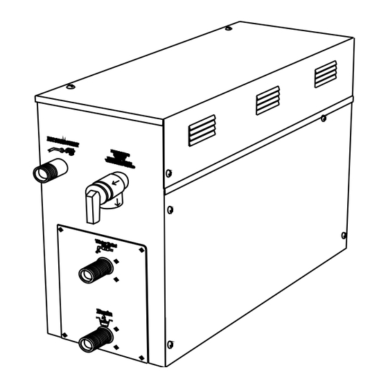
F us e for w ire pow er s upply C o n tro ller w ire P ow er w ire hole an d lig h t w ir e hole Fuse for wire power supply 6kW/7.5kW/9kW Page 12 SteamSpa PHONE: 800-856-0172 FAX: 866-560-1060 http://steamspa.com info@steamspa.com... -
Page 13: Electrical Requirements
3. Connect suitably sized equipment grounding wire into the ground terminal. 4. All the connections must be in accordance with national and local electricity consumption codes and be installed by professional electricians. Page 13 SteamSpa PHONE: 800-856-0172 FAX: 866-560-1060 http://steamspa.com info@steamspa.com... -
Page 14: Assembly Graph For Power Wire
To avoid damage to the equipment, do not connect electric current directly to heating elements. WARNING! This graph is for explanation only. For actual installation, refer to national and local electricity consumption codes by professional electricians. Page 14 SteamSpa PHONE: 800-856-0172 FAX: 866-560-1060 http://steamspa.com info@steamspa.com... -
Page 15: Wiring Diagrams (Generator Unit)
Ye l l ow / G re e n B l a c k Black Black R e d Black R e d Black B l a c k B l a c k R e d Page 15 SteamSpa PHONE: 800-856-0172 FAX: 866-560-1060 http://steamspa.com info@steamspa.com... -
Page 16: Installation Of The Top Light
4 5 mm be exposed to moisture, as it will cause damage to the light components causing a possible short circuit. Rubber G as ket Ceiling of s team room LED light Page 16 SteamSpa PHONE: 800-856-0172 FAX: 866-560-1060 http://steamspa.com info@steamspa.com... -
Page 17: Steam Generator Dissection Diagram
9. MAIN WATER TANK 15. GROUND WIRE CONNECTOR 4. STEAM OUTLET 10. HEATING ELEMENT 16. RELAY 5. PRESSURE RELIEF VALVE 11. 221 F HI-LIMIT 17. WATER LEVEL SENSOR 6. WATER FILL VALVE 12. TRANSFORMER Page 17 SteamSpa PHONE: 800-856-0172 FAX: 866-560-1060 http://steamspa.com info@steamspa.com... -
Page 18: Care & Use For The Control Panel
Do not route control wiring inside or close to power lines conduit, hot water or steam piping. Doing so may result in an inoperative control, generator, and/or hazardous installation. Do not install SteamSpa controls with other than SteamSpa compatible steam generators. Doing so may result in possible generator damage or inoperative installation. -
Page 19: Control Panel Installation Instructions
ATTENTION!: Avoid bending the pins inside the cable connection the control panel and steam generator. Make sure the arrows on the male and female ends are lined up as illustrated below. Page 19 SteamSpa PHONE: 800-856-0172 FAX: 866-560-1060 http://steamspa.com info@steamspa.com... -
Page 20: Testing The Machine (Round Control)
10. TEMP SENSOR 1. POWER ON/OFF 2. TIME/TEMP SET ON DUAL SYSTEMS) 3. TIME/TEMP DECREASE 7. DIGITAL DISPLAY SCREEN 4. TIME/TEMP INCREASE 8. STEAMSPA LOGO 5. LIGHT ON/OFF 9. FRONT DECORATIVE BEZEL Page 20 SteamSpa PHONE: 800-856-0172 FAX: 866-560-1060 http://steamspa.com info@steamspa.com... -
Page 21: Control Panel Operation
(Fig.6). When the light is turned off, the digital tube will temporarily display (Fig.7). Screen will turn to display ambient TEMP if no operation is Fig.7 selected in 5 seconds. Page 21 SteamSpa PHONE: 800-856-0172 FAX: 866-560-1060 http://steamspa.com info@steamspa.com... -
Page 22: Testing The Machine (Touch Pad)
Do not touch the safety release valve while the generator is running. CONTROL PANEL DIAGRAM 1. TEMP DISPLAY SCREEN 6. MEMORY 2. TIME DISPLAY SCREEN 7. LIGHT ON/OFF 3. TIME/TEMP DECREASE 8. POWER ON/OFF 4. TIME/TEMP INCREASE 5. TIME/TEMP SET Page 22 SteamSpa PHONE: 800-856-0172 FAX: 866-560-1060 http://steamspa.com info@steamspa.com... -
Page 23: Control Panel Operation
. When the light is turned off, the digital tube will temporarily display . Screen will turn to display ambient TEMP if no operation is selected in 5 seconds. Page 23 SteamSpa PHONE: 800-856-0172 FAX: 866-560-1060 http://steamspa.com info@steamspa.com... -
Page 24: Installation Of Control Panel
Installation of control panel and TEMP sensor Recess mount into wall 3.9 inches 5.6 inches Open square notch by 3.9x5.6 inch to steam generator sensor control panel Screw 3.9 feet to 4.5feet high from the ground Page 24 SteamSpa PHONE: 800-856-0172 FAX: 866-560-1060 http://steamspa.com info@steamspa.com... - Page 25 TEMP sensor S tick on the wall drill a round hole 1.378 inches to steam generator sensor control panel stick 4feet to 4.5feet high f rom the ground sealant Page 25 SteamSpa PHONE: 800-856-0172 FAX: 866-560-1060 http://steamspa.com info@steamspa.com...
-
Page 26: Installation Of Temperature Sensor
Controller oof rating CONTROLLER SIZE AND WATERPROOF RATING Control panel model GS1090C(single panel) GS1090D(dual panel) Panel size 5.9x3.5x1 inches 5.9x3.5x1 inches ( length*width*height) Waterproof rating I P54 I P54 Page 26 SteamSpa PHONE: 800-856-0172 FAX: 866-560-1060 http://steamspa.com info@steamspa.com... -
Page 27: Steam Generator Maintenance
Label each electrical connections then carefully remove all connections. d. With a wrench or a 32mm ratchet socket carefully unscrew the water senor. e. Thoroughly clean any residue buildup accumulated on the prong. Page 27 SteamSpa PHONE: 800-856-0172 FAX: 866-560-1060 http://steamspa.com info@steamspa.com... -
Page 28: Troubleshooting
Hot water is coming from the steam 1. The water inlet valve may have by switching on/off a few times to head residue buildup inside dislodge the buildup 2. Replace the water inlet valve Page 28 SteamSpa PHONE: 800-856-0172 FAX: 866-560-1060 http://steamspa.com info@steamspa.com... - Page 29 1. Make sure all cables to the heating The control panel shows the loose elements are well connected temperature, but does not go on 2. The heating element is 2. Replace the heating element malfunctioning Page 29 SteamSpa PHONE: 800-856-0172 FAX: 866-560-1060 http://steamspa.com info@steamspa.com...
-
Page 30: Technical Parameters
The list above is for reference only. Actual checking and repairing should be based on national and local codes, ask professional service personnel to operate. IMPORTANT! The parameter listed above will vary by geographical location and environment. Please consult a qualified designer and architect for more detailed use. Page 30 SteamSpa PHONE: 800-856-0172 FAX: 866-560-1060 http://steamspa.com info@steamspa.com... -
Page 31: Wiring Diagrams (Control Unit)
WIRING DIAGRAMS 4.5KW Control panel(outside room) Control panel(inside room) 240V~ Page 31 SteamSpa PHONE: 800-856-0172 FAX: 866-560-1060 http://steamspa.com info@steamspa.com... - Page 32 Control panel(outside room) Control panel(inside room) 240V Page 32 SteamSpa PHONE: 800-856-0172 FAX: 866-560-1060 http://steamspa.com info@steamspa.com...
- Page 33 7.5KW & 9KW Control panel(outside room) Control panel(inside room) 240V~ Page 33 SteamSpa PHONE: 800-856-0172 FAX: 866-560-1060 http://steamspa.com info@steamspa.com...
- Page 34 10.5KW & 12KW Control panel(outside room) Control panel(inside room) 240V Page 34 SteamSpa PHONE: 800-856-0172 FAX: 866-560-1060 http://steamspa.com info@steamspa.com...
- Page 35 15KW Control panel(outside room) Control panel(inside room) 240V Page 35 SteamSpa PHONE: 800-856-0172 FAX: 866-560-1060 http://steamspa.com info@steamspa.com...
- Page 36 5x6x7 12kw 5x7x7 12kw 5x8x7 12kw 5x9x7 12kw *Cabin dimensions are based on WxLxH NOTE: It’s safe and even recommended to use a generator size, 1-step higher than what the chart indicates. Steam Spa PHONE: 800-856-0172 FAX: 866-560-1060 http://steamspa.com info@steamspa.com...
Need help?
Do you have a question about the Oasis OA750CH and is the answer not in the manual?
Questions and answers