Table of Contents
Advertisement
Quick Links
INSTALLATION INSTRUCTIONS
BE5C
This is a safety alert symbol and should never be ignored. When you see this symbol on labels or in manuals, be alert to
the potential for personal injury or death.
Improper installation, adjustment, alteration, service
or maintenance can cause property damage, personal
injury or loss of life. Installation and service must be
performed by a licensed professional HVAC installer or
equivalent, service agency, or the gas supplier.
IMPORTANT
The Clean Air Act of 1990 bans the intentional venting
of refrigerant (CFCs, HCFCs and HFCs) as of July
1, 1992. Approved methods of recovery, recycling or
reclaiming must be followed. Fines and/or incarceration
may be levied for noncompliance.
507787B02
This manual must be left with the homeowner for future reference.
WARNING
One-Piece PSC Air Handler
Table of Contents
Unit Dimensions - Upflow - Inches (mm) ...................2
Shipping and Packing List ...........................................3
General ........................................................................3
Requirements ..............................................................3
Use of Air Handler During Construction.......................4
Installation Clearances ................................................4
Installation ...................................................................4
Condensate Drain........................................................7
Duct System and Filters ..............................................9
Brazing Refrigerant Lines ............................................9
Sealing the Unit .........................................................11
Electrical Connections ...............................................11
Air Flow - Cooling Blower Speed ..............................16
Checkout Procedures ................................................18
Operation ...................................................................18
Repairing or Replacing Cabinet Insulation ................19
Professional Maintenance .........................................20
Homeowner Maintenance..........................................20
As with any mechanical equipment, contact with sharp
sheet metal edges can result in personal injury. Take
care while handling this equipment and wear gloves
and protective clothing.
*P507787B02*
Issue 2336
CAUTION
Blue Summit LLC
8201 C National Turnpike
Louisville, KY 40214
(P) 507787B02
Page 1 of 22
Advertisement
Table of Contents

Related Manuals for Blue Summit BLUERIDGE BE5C

Summary of Contents for Blue Summit BLUERIDGE BE5C
-
Page 1: Table Of Contents
HVAC installer or and protective clothing. equivalent, service agency, or the gas supplier. Blue Summit LLC 8201 C National Turnpike Louisville, KY 40214 IMPORTANT The Clean Air Act of 1990 bans the intentional venting... -
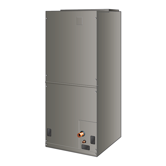
Page 2: Unit Dimensions - Upflow - Inches (Mm)
Unit Dimensions – Upflow – Inches (mm) 1 (25) DETAIL OF PIPING PLATE 4-3/4 3/4 (19) (121) SUCTION LINE SUPPLY AIR LIQUID OPENING CONDENSATE LINE 14-1/2 DRAINS (2) (368) 2-3/8 (Horizontal) (60) 1 (25) 1 (25) CONDENSATE DRAINS (2) 4-3/8 (Upflow and (111) 2-3/4... -
Page 3: Shipping And Packing List
In addition to conforming to manufacturer’s installation Shipping and Packing List instructions and local municipal building codes, installation of air handler units (with or without optional electric heat), Package 1 of 1 contains: MUST conform with National Fire Protection Association (NFPA) standards: “Standard for Installation of Air 1 –... -
Page 4: Use Of Air Handler During Construction
VOIDS MANUFACTURER’S conduit opening. This will also keep warm and moist EQUIPMENT LIMITED WARRANTY. BLUE SUMMIT unconditioned air out of the air handler cabinet where DISCLAIMS ALL LIABILITY IN CONNECTION WITH it will form condensate on the cooler control box and INSTALLER’S FAILURE TO FOLLOW THE ABOVE... - Page 5 For ease in installation, it is best to make any necessary NOTE: When the unit is installed in horizontal applications, coil configuration changes before setting air handler in a secondary drain pan is recommended. Refer to local place. codes. NOTE: This unit may be installed in left-hand or right-hand Refrigerant Metering Device air discharge horizontal applications.
- Page 6 Rotate drip shield 180° front-to-back. Left-Hand Air Discharge For horizontal left-hand air discharge, the following field Remove plastic plug from left hole on coil front end seal and reinstall plug in back hole. Reinstall drip modifications are required. shield screw in front coil end seal. Drip shield should drain downward into horizontal drain pan inside coil.
-
Page 7: Condensate Drain
Sloping The Unit 13. Set unit so that it is sloped 1/4ʺ toward the drain pan end of the unit. Connect return and supply air plenums Make sure the unit is sloped (similar to the slope shown as required using sheet metal screws. in Figure 6) so that the drain pan will empty completely without water standing in the pan. - Page 8 water draining from the outlet will be easily noticed being pulled through the condensate line will not allow by the homeowner. Refer to local codes for drain trap positive drainage without a proper trap. requirements on the secondary drain line. Route the drain line to the outside or to an appropriate Check again to ensure drain ports and drain pan are drain.
-
Page 9: Duct System And Filters
Field-Fabricated Return Air Duct Flange for Duct System and Filters Horizontal Applications A return air duct system is recommended, but not factory- provided. If the unit is installed in a confined space or Duct System closet, run a full-size return connection to a location outside The air handler is provided with flanges for the connection the closet. - Page 10 PLEASE READ IMPORTANT ISSUES CONCERNING BRAZING OPERATIONS IN THE BRAZING REFRIGERANT LINES SECTION BEFORE PROCEEDING. NOTE - Refer to outdoor unit installation instructions for refrigerant piping size requirements. NOTE - Use silver alloy brazing rods with five or six percent minimum silver alloy for copper-to-copper brazing;...
-
Page 11: Sealing The Unit
Run 24V Class II wiring only through specified low Recommended line length is 50’ or less. If more than 50’ voltage opening. Run line voltage wiring only through line set is required, contact Blue Summit. specified high voltage opening. Do not combine voltage in one opening. - Page 12 • This unit is provided with holes for conduit. Use provided caps to seal holes not used. WARNING • Typical unit wiring (as well as wiring of optional field- Electric Shock Hazard. Can cause injury or installed electric heat) is given in Figure 16. Refer to death.
- Page 13 208 / 240 VOLT TRANSFORMER PRIMARY SECONDARY 240 Volts 208 Volts Figure 14. Converting Unit from 240VAC to 208VAC Thermostat Indoor Unit Outdoor Unit Figure 12. Notch for Control Panel Relocation Auxiliary Heat Auxiliary Heat (Heat Pump) (Heat Pump) SIDE Indoor Blower Only Heat Pump Compressor / 1st Stage...
- Page 14 4KW & 5KW Figure 16. Typical Wiring Diagram – BE5C Air Handler with Electric Heat – PSC (018, 024, 030, 036, 042 models) Page 14 of 22 Issue 2336 507787B02...
- Page 15 PART NO. 537981-03 WIRING DIAGRAM - ELECTRIC HEAT 20KW HTR 3 HTR 2 HTR 1 HTR 4 SEC L SEC L SEC L SEC L HTR 2 HTR 4 HTR 3 HTR 1 PRI LS PRI LS PRI LS PRI LS 12.5KW &...
-
Page 16: Air Flow - Cooling Blower Speed
Change Blower Speed Air Flow – Cooling Blower Speed Disconnect all power supplies. Remove the air handler access panel. The cooling blower speed is factory configured to provide IMPORTANT: For -048 and -060 units, disregard step 3. correct air flow for an outdoor unit that matches the cooling capacity rating of the air handler. - Page 17 Air Handler Model Blower Speed .10" WC .20" WC .30" WC .40" WC .50" WC -018 HIGH -024 1011 HIGH 1106 1045 -030 1078 1057 1024 HIGH 1311 1261 1214 1154 1086 1020 -036 1276 1240 1191 1148 1086 HIGH 1559 1521 1446...
-
Page 18: Checkout Procedures
Check Electric Heat (If Used) Checkout Procedures 1. Set thermostat to call for auxiliary heat (approximately 5°F above ambient temperature). The indoor blower NOTE: Refer to outdoor unit installation instructions for and auxiliary heat should come on together. Allow a system start-up instructions and refrigerant charging minimum of 3 minutes for all sequencers to cycle on. -
Page 19: Repairing Or Replacing Cabinet Insulation
Heating (Electric Heat Only) Repairing or Replacing Cabinet Insulation When the thermostat calls for heat, the circuit between R and W is completed, and the heat sequencer is energized. A time delay follows before the heating elements and the indoor blower motor come on. Units with a second heat IMPORTANT sequencer can be connected with the first sequencer to W DAMAGED INSULATION MUST BE REPAIRED OR... -
Page 20: Professional Maintenance
Professional Maintenance Homeowner Maintenance NOTICE IMPORTANT Failure to follow instructions will cause damage to the Do not operate system without a filter. A filter is required unit. to protect the coil, blower, and internal parts from excessive dirt and dust. The filter is placed in the return This unit is equipped with an aluminum coil. - Page 21 Installing Contractor’s Name_______________________ Installing Date_______________________________ Installing Contractor’s Phone_______________________ Air Handler Model #___________________________ Job Address____________________________________ Thermostat Line Voltage SUPPLY Disconnect Switch Temperature Integrated Control Duct Blower Motor Amps System Electric Heat Amps Duct Static RETURN Filter Drain Line DUCT SYSTEM TOTAL EXTERNAL STATIC (dry coil) dry coil wet coil SUPPLY AIR DUCT...
- Page 22 Installing Contractor’s Name_______________________ Installing Date_______________________________ Installing Contractor’s Phone_______________________ Air Handler Model #___________________________ Job Address____________________________________ Line Voltage Disconnect Switch Thermostat Integrated Control Duct System Duct System Filter RETURN SUPPLY Electric Heat Amps Blower motor Amps Drain Line Duct Static Temperature DUCT SYSTEM TOTAL EXTERNAL STATIC (dry coil) dry coil wet coil...
Need help?
Do you have a question about the BLUERIDGE BE5C and is the answer not in the manual?
Questions and answers