
Subscribe to Our Youtube Channel
Related Manuals for ALTHEN FDRF603 Series


Summary of Contents for ALTHEN FDRF603 Series
- Page 1 Laser Triangulation sensors FDRF603 Series Manual FDRF603 Series Valid for sensors with serial numbers 19300 and higher Certified according to ISO 9001:2008...
-
Page 2: Table Of Contents
Contents Safety precautions ........................….……………..4 Electromagnetic compatibility....................….…………..4 Laser safety..........................….…….………...4 3.1. Class 3B sensors..................….…….………......4 3.2. Class 3R sensors ....................….…..………....5 3.3. Class 2 sensors ......................….……………....5 3.4. Class 1 sensors ......................….……………....5 General information......................….…..………....6 Basic technical data ..................….…..………........6 Example of item designation when ordering .............….….…........7 Structure and operating principle .................….….……......7 Dimensions and mounting..................….…………......8 8.1. - Page 3 14.1. Current output 4…20 mA....................….…..…...…..18 14.2. Voltage output .....................….……………....19 14.3. Configuration parameters ................….…….……......19 14.3.1. Range of the analog output ..............….………......19 14.3.2. Analog output operation mode..............….………....19 14.4. Factory parameters table..................….….….……....19 Request codes and list of parameters ..............….…..….….......19 15.1. Request codes table..................….…..…..…….......19 15.2. List of parameters.....................….……………......20 15.3.
-
Page 4: Safety Precautions
Safety precautions • Use supply voltage and interfaces indicated in the sensor specifications. • In connection/disconnection of cables, the sensor power must be switched off. • Do not use sensors in locations close to powerful light sources. • To obtain stable results, wait about 20 minutes after sensor activation to achieve uniform sensor warm-up. -
Page 5: Class 3R Sensors
• Use the protective screen mounted on the sensor for the blocking of the outgoing beam; • Use the laser deactivation function in emergency. 3.2. Class 3R sensors The sensors make use of an c.w. 660 nm wavelength semiconductor laser. Maximum output power is 5 mW. -
Page 6: General Information
General information The sensors are intended for non-contact measuring and checking of position, displacement, dimensions, surface profile, deformation, vibrations, sorting and sensing of technological objects as well as for measuring levels of liquid and bulk materials. The series includes 26 sensors with the measurement range, from 2 to 1250 mm and the base distance from 10 to 260 mm. -
Page 7: Example Of Item Designation When Ordering
Example of item designation when ordering FDRF603(BLUE)(L/P)-X/D(R)-SERIAL-ANALOG-IN-AL-CC(R)(90)-M-H-P-B Symbol Description (BLUE) Blue (405 nm) laser option L or P – attribute showing Laser safety Class 2 or Class 3B Base distance (beginning of the range), mm Measurement range, mm Round shape laser spot (see p.19.3.) SERIAL The type of serial interface: RS232-232 or RS485-485 or (CAN and RS232) - CAN, or (Ethernet and RS232) –232-ET or (Ethernet and RS485) –... -
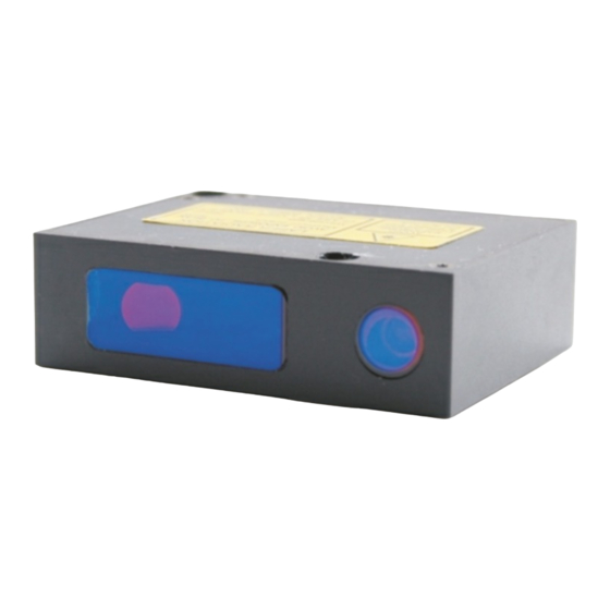
Page 8: Dimensions And Mounting
Dimensions and mounting 8.1. Overall and mounting dimensions Overall and mounting dimensions of the sensors are shown in Figure 2 and 2.1. Sensor package is made of anodized aluminum. The front panel of the package has two Glass windows: one is output, the other for receiving radiation reflected from the object under control. -
Page 9: Mounting Of The Sensors For Mirror Surface Control
8.2. Mounting of the sensors for mirror surface control Fig. 4 shows the requirements for the mounting of the RF603-R-39/4 sensor for control of mirror objects and glass. The special mounting device is included into the shipping, figure 5. Figure 4 Figure 5 8.3. -
Page 10: Cables
Designation of contacts is given in the following tables: Connector #1 Model of the sensor Pin number Assignment Gnd (power supply) (CAN/ET)-232-U/I-IN-AL Gnd (Common for signals) Power U+ Gnd (power supply) DATA+ (ET)-485-U/I-IN-AL DATA- Gnd (Common for signals) Power U+ Connector #2 Model of the sensor Pin number... -
Page 11: Configuration Parameters
White-orange Orange White-green RJ-45 Green CAN_H White-orange free leads CAN_L Orange Green Configuration parameters The nature of operation of the sensor depends on its configuration parameters (operation modes), which can be changed only by transmission of commands through serial port RS232 or RS485. The basic parameters are as follows: 10.1. -
Page 12: The Point Of Zero
Result. The time interval value is set in increments of 0.01 ms. for the For example, parameter value equal to 100, data are transmitted through bit-serial interface with a period of 0,01*100 = 1 ms. If the Trigger Sampling mode is selected, the ‘sampling period’ parameter determines the division factor for the external synchronization input. -
Page 13: Time Lock Of The Result
Out of the range indication Mutual synchronization Hardware zero-set/ Hardware laser ON/OFF +24VDC +24VDC Figure 6.1 Figure 6.2 Figure 6.3 10.6. Time lock of the result If the sensor does not find out object or if the authentic result cannot be received, zero value is transferred. -
Page 14: Description Of Rs232 And Rs485 Interfaces
Method of results averaging Over a number of results Number of averaged values The parameters are stored in nonvolatile memory of the sensor. Correct changing of the parameters is carried out by using the parameterization program supplied with the sensor or a user program. Description of RS232 and RS485 interfaces 11.1. -
Page 15: Interfacing Protocol
11.5. Interfacing protocol 11.5.1. Serial data transmission format Data message has the following format: 1 start-bit 8 data bits 1 even bit 1 stop-bit 11.5.2. Communication sessions types The communications protocol is formed by communication sessions, which are only initiated by the ‘master’ (PC, controller). There are two kinds of sessions with such Structures: 1) “request”, [“message”] —... -
Page 16: Data Stream
counter is incremented by the sending of each burst and is used for formation (assembly) of batches or bursts as well as for control of batch losses in receiving data streams. The following is the format of two ‘answer’ data bursts for transmission of byte: DAT(7:0) Byte 0 Byte 1 CNT(1:0) DAT(3:0) CNT(1:0) DAT(7:4) 11.5.6. -
Page 17: Factory Parameters Table
sensor is set with standard or extended identifier which is unique for a network given. The number of sensors in the network is up to 112. 12.2.3. Factory parameters table Parameter Value Data transmission rate 125 kb/s Standard identifier 7FFh Extended identifier 1FFFFFFFh Interface condition... -
Page 18: Data Structure
........... - byte 501, byte 502: measurement - byte 503,... -
Page 19: Voltage Output
14.2. Voltage output The connection scheme is shown in the figure. To reduce noise, it is recom- mended to install RC filter before the measuring instrument. The filter capacitor value is indicated for maximum sampling frequency of the sensor (9,4 kHz) and this value in- creases in proportion to the frequency reduction. -
Page 20: List Of Parameters
–range Reading of parameter - code of parameter (1) - value of parameter Writing of parameter - code of parameter — - value of parameter Storing current parameters to - constant (1) - constant FLASH-memory Recovery of parameter default - constant (1) - constant values in FLASH-memory Latching of current result... -
Page 21: Notes
Higher byte for the beginning of analog output range Lower byte for the end of analog 0…4000h, (default — 4000h) ) specifies a point within the absolute output range range of transducer where the analog output has a maximum Higher byte for the end of analog value output range Time lock of result... -
Page 22: Examples Of Communication Sessions
data transfer. This request can be sent simultaneously to all sensors in the net in the broadcast mode in order to synchronize data pickup from all sensors. · When working with the parameters, it should be borne in mind that when power is OFF the parameter values are stored in nonvolatile FLASH-memory of the sensor. - Page 23 Base distance DAT(7:0) Byte 0 Byte 1 DAT(7:0) Byte 0 Byte 1 Measurement range DAT(7:0) Byte 0 Byte 1 DAT(7:0) Byte 0 Byte 1 Note: as bust number =1, then CNT=1 2) Request "Reading of parameter". Condition: device address —1, request code – 02h, code of parameter — 05h, value of parameter —...
-
Page 24: Parameterization Program
Parameterization program 16.1. Function The FDRF60X-SP-2.0 software is intended for: 1) Testing and demonstration of work of FDRF603 series sensors; 2) Setting of the sensor parameters; 3) Reception and gathering of the sensor data signals 16.2. Program setup Start file RF603setup.exe and follow instructions of the installation wizard 16.3. -
Page 25: Checking Of The Sensor Operability
If connection is not established, a prompt will appear asking to make automatic search of the sensor: To start search, press the Yes button · set the range of transmission rate search in the Baud rate line · set the range of network address search in the Net address line ·... -
Page 26: Connection Through Ethernet Interface
· by pressing the Request button, obtain the result of one measurement on the (Current result) indicator. The 06h request type is realized (see par. 15.1). · pressing the Stream button will switch the sensor to the data stream trans- mission mode. -
Page 27: Display, Gathering And Scanning Of Data
16.6. Display, gathering and scanning of data Measurement result is displayed in digital form and in the form of oscillogram and is stored in the PC memory. · the number of points displayed along the X co-ordinate can be set in the Number of points in buffer window;... - Page 28 Setting RS232/RS485 Setting CAN Setting Ethernet Setting analog outputs Setting of all configuration parameters of the sensor is possible with the help of the respective panel (Sensor configuration parameters): Page 28/34...
-
Page 29: Automatic Data Stream Mode After Power Switch On
16.7.2. Automatic data stream mode after power switch on By default, after power supply switch on the sensor is waiting for request result command. To get continuous data stream after power supply switch on mark Auto stream box. Save parameters (see below). Now with any subsequent activation of the sensor it will work in data stream mode. -
Page 30: Appendix
Software Description Service User software for work with laser sensors, parameter setting, and data acquisition program (parameter- ization pro- gram) FDRF Device Designed for work with all similar devices. Includes: Software · Support of MSVC and BorlandC for Windows, Linux, Wrapper C#, Wrapper Dephi. -
Page 31: Spray Guard
18.2. Spray guard The spray guard is intended to reduce dirtying of the sensor windows. Overall dimensions are shown in Fig. 8 Figure 8 18.3. Size of the laser spot and mounting space The laser spot dimensions for two device modifications (elliptical spot and round spot) as well as parameters characterizing required space for the passing of laser beams are given in the table and explained in the figure 9 (names: SMR –... -
Page 32: Connector Mounting Options
Figure 9 18.4. Connector mounting options Overall dimensions of a cable connector sensor are shown in Fig 10, 12 and mounting options for 90 degree connector are shown in Fig.11 and Fig.13. Figure 10 Page 32/34... - Page 33 Figure 11 Figure 12 Page 33/34...
-
Page 34: Warranty Policy
The information provided herein is to the best of our knowledge true and accurate, it is provided for guidance only. All specifications are subject to change without prior notification. Althen – Your expert partner in Sensors & Controls | althensensors.com Althen stands for pioneering measurement and custom sensor solutions. In addition we offer services such as calibration, design & engineering, training and renting of measurement equipment. Germany/Austria/Switzerland...
Need help?
Do you have a question about the FDRF603 Series and is the answer not in the manual?
Questions and answers