Table of Contents
Advertisement
Quick Links
Advertisement
Table of Contents

Related Manuals for VELIT 2000U


Summary of Contents for VELIT 2000U
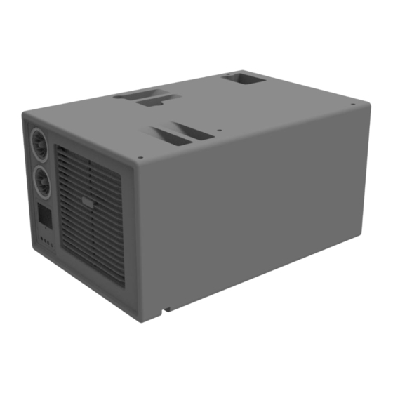
- Page 1 DC Under-bench Air Conditioner Instruction Manual Page...
-
Page 2: Table Of Contents
The latest electronic version of this document is available for download on the product page. We hope you enjoy your new Velit air conditioner. For any product questions or issues, you can reach out to us at support@velitcamping.com... -
Page 3: Important Safety Information
● Keep electrical devices out of reach of children and do not allow them to operate the device without supervision. ● Only use accessories authorized by Velit. ● Do NOT use this unit in or near flammable environment. ● Do NOT let children use the unit without supervision ●... -
Page 4: Specifications
2.SPECIFICATIONS Model 2000U Input Voltage Operating Current 20-60A 10-33A 5-15A Cooling Capacity 8000BTU/2200W Air Flow Rate 400mc/h Rated Power 700W Refrigerant R134a 400g Eco mode: 50dB Noise Level Boost mode: 60dB Dimension 23.8” L x 16.2” W x 11.8”H Weight 36.4lb... -
Page 5: Accessories
3.ACCESSORIES 1. Air Vent 2. Air Duct Clamp 3. Air Duct 4. External Control Panel 5. Exhaust Duct Clamp 6. Exhaust Duct 7. Exhaust Vent 8. L Drain Hose Adaptor 9. Drain Hose Parts Quantity Corner Bracket with Screws 100mm Exhaust Duct (4ft) Exhaust Vent Exhaust Duct Clamp Duct mounting plate... -
Page 6: Installation
4.INSTALLATION When drilling into the vehicle body, make sure to check the other side and avoid drilling into other components/wiring. Always apply sealant/paint to bare metal around the cut surface to prevent rust. Make sure to disconnect all power supplies to the vehicle including battery, generator, and shore power prior to installation. -
Page 7: Exhaust Vent
4.1 Exhaust Vent Locate the exhaust vent location using the cutting template. Three configurations are available to choose from: One Rectangular hole Exhaust and intake vents can be mounted together using the metal plate and six screws. For this configuration, a rectangular hole needs to be cut. This approach is easier and faster for installation. - Page 8 Vent through the floor: • Leave enough room for the vent and the unit. • Make sure the vent location has free airflow and is free of direct obstruction within 8 inches. • Make sure the fins on the vents do not point at each other. •...
- Page 9 • Place the vent over the opening. Secure the vent to the floor with four self-tapping screws. • Apply sealant to the edge of the vent if needed. Vent through the wall • Leave enough room for the vent and the unit. Page...
- Page 10 • Follow the UP icon, the vents must be installed as shown. • Make sure the vent location has free airflow and is free of direct obstruction within 8 inches. • Cut the opening using the template. Apply sealant/paint to any bare metal edges. •...
- Page 11 • Apply sealant along the edge of the vent and press it over the opening. • On the inside, place the trim over the opening. Use self-tapping screws to secure the inside vent piece to the outside vent piece. • Connect the ducts to the unit. Use hose clamp to secure the duct •...
-
Page 12: Drain Line
4.2 Drain Line • The drain hose can be installed to exit the unit from either the front or the side. • Insert the L hose adaptor into the drain outlet in the desired position. • If the drain outlet exits the front of the unit, connect the drain line to the outlet before securing the unit to the floor because the outlet will not be accessible once the unit is secured in place. -
Page 13: Unit
4.3 Unit NOTICE The unit location needs to have proper airflow with the interior space. If the unit is installed inside of a cabinet, a 5”x 5” or similar size vent hole may need to be cut if insufficient air flow is noticed during the test run section later. -
Page 14: Air Duct (Optional)
4.4 Air Duct (Optional) Air vents can be directly mounted on the unit or ducts can be attached to distribute the cool air to different areas. If using the included ducts, drill 2.5-inch holes to install the vents in the desired location. 4.5 External Control Panel (Optional) The external control panel can be connected for easier access and better remote reception. -
Page 15: Test Run
4.6 Test Run • Leave the access panel/ cabinet door open. • Turn on the unit and set the fan speed to max. • Listen to the sound/ pitch of the blower fan and feel the air volume. • Close the access panel/ cabinet door. •... -
Page 16: Operation
5.OPERATION 5.1 Modes Mode changes only change the compressor speed. Fan speed can be adjusted separately. Output from low to high: Sleep : ECO : Cooling : TURBO : 5.2 External Control Panel 1 - Power ON/OFF: short press to turn on the unit. Long press for two seconds to turn off the unit. -
Page 17: Internal Control Panel
5.3 Internal Control Panel 1 – Power/Mode: short press to turn on the unit. When unit is on, short press to cycle through modes. Long press two seconds to turn off the unit. Long press ten seconds to reset to factory default setting. 2 - Temperature +: Increase setting temperature 3 - Temperature -: Decrease setting temperature 4 - Fan Speed: Cycle through 5 fan speeds... -
Page 18: Remote Control
5.4 Remote Control This is a general-purpose remote. Some buttons do not apply to this model : Turn ON/OFF :Switch between modes :Change fan speed :Increase temp :Decrease temp :Sleep mode :ECO mode :Cooling mode :Turbo mode :View voltage :Timer :N/A :N/A :N/A... -
Page 19: Switch Display Unit °C/°F
5.5 Switch Display Unit °C/°F This feature is only available to units that come with display remote control. When the unit is powered off, on the remote control, short press the mode button and down arrow button at the same time. The display unit on the remote will switch. Turn the unit on with the remote and the unit on the display panel will sync with the remote. -
Page 20: Troubleshooting
6.TROUBLESHOOTING 6.1 Error code There are multiple sensors built inside the unit. When an error is detected, the error icon will flash with the error code displayed. Check the table below for the meaning of the error codes and contact customer service when needed. Code Cause Troubleshooting... -
Page 21: Unit Not Cooling
6.2 Unit not cooling Turn on the unit and use a pressure gauge to measure the pressure at the low-pressure port. Use this chart to find the nominal pressure value based on the ambient temperature. If the pressure is lower than the nominal value, use a R134a recharge kit (can be purchased from Auto part stores and Home Depot) to charge the unit to the desired pressure. - Page 22 22 | Page...
Need help?
Do you have a question about the 2000U and is the answer not in the manual?
Questions and answers