
Subscribe to Our Youtube Channel
Related Manuals for Gema OptiFlow IG07-P


Summary of Contents for Gema OptiFlow IG07-P
- Page 1 Rev. 00 1011 536 Operating instructions and Spare parts list Powder injector OptiFlow IG07-P Translation of the original operating instructions...
- Page 2 To the best of our knowledge and belief, the information contained in this publication was correct and valid on the date of publication. Gema Switzerland GmbH makes no representations or warranties with respect to the contents or use of this publication, and reserves the right to revise this publication and make changes to its content without prior notice.
-
Page 3: Table Of Contents
Requirements on personnel carrying out the work ........21 Disposal regulations ................. 21 Materials ....................21 Spare parts list Ordering spare parts ..................... 23 OptiFlow IG07-P – Spare parts list ............... 24 OptiFlow IG07-P – spare parts ................25 Table of contents 3 OptiFlow IG07-P... - Page 4 Rev. 00 02/19 4 Table of contents OptiFlow IG07-P...
-
Page 5: About These Instructions
General information This operating manual contains all important information which you require for the working with the OptiFlow IG07-P. It will safely guide you through the start-up process and give you references and tips for the optimal use when working with your powder coating system. -
Page 6: Structure Of Safety Notes
Presentation of the contents Figure references in the text Figure references are used as cross references in the descriptive text. Example: "The high voltage (H) created in the gun cascade is guided through the center electrode." 6 About these instructions OptiFlow IG07-P... -
Page 7: Safety
If this product is to be used for other purposes or other substances outside of our guidelines then Gema Switzerland GmbH should be consulted. -
Page 8: Product Specific Security Regulations
The installation work to be done by the customer must be carried out according to local regulations. – It must be ensured, that all components are earthed according to the local regulations before start-up. For further security information, see the more detailed Gema safety regulations! 8 Safety OptiFlow IG07-P... -
Page 9: Product Description
Any other use is considered non-compliant. The manufacturer is not responsible for any incorrect use and the risks associated with such actions are assumed by the user alone! Product description 9 OptiFlow IG07-P... -
Page 10: Reasonably Foreseeable Misuse
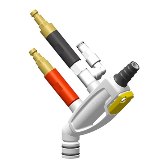
The injector is supplied with a PTFE / ETFE cartridge as standard. Structure Overall view Fig. 2 Check valve unit Release trigger (supplementary air) Check valve unit Powder hose quick release (conveying air) connection Powder hose rinsing Powder hopper connection connection Injector housing 10 Product description OptiFlow IG07-P... -
Page 11: Principle Of The Injector
The transport of fine solids such as powder requires a certain air volume per time unit to facilitate airborne conveyance. If a hose diameter of 11 mm is used, the value is approx. 4 Nm³/h. If the powder transport becomes irregular, the so-called "pumping" takes place. Product description 11 OptiFlow IG07-P... -
Page 12: Powder Volume Setting For Optiflow Injector
Powder output (reference values) General conditions for the OptiFlow Injector Powder type Epoxy/polyester Powder hose Ø (mm) Type of powder hose POE with guide strips Input pressure OptiStar (bar) Powder output zeroing Correction value C0 adjustment 12 Product description OptiFlow IG07-P... -
Page 13: Available Accessories
Total air volume (Nm³/h) Powder output (g/min) Powder output 135 150 100 185 215 145 235 270 185 280 320 220 Available accessories – Multi-Tool / Plug gauge for checking wear (order no. 1017 201) Product description 13 OptiFlow IG07-P... - Page 14 Rev. 00 02/19 14 Product description OptiFlow IG07-P...
-
Page 15: Maintenance / Repairs
Clean the injector body with compressed air which is free of oil and water. – Any contamination can be seen through the opening of the hopper fitting If the injector is severely fouled, it must be dismantled Maintenance / Repairs 15 OptiFlow IG07-P... - Page 16 Reinsert the injector and fix it fig. 4 Check valve unit Release trigger (supplementary air) Check valve unit Powder hose quick release (conveying air) connection Powder hose rinsing Powder hopper connection connection Injector housing 16 Maintenance / Repairs OptiFlow IG07-P...
-
Page 17: Cleaning The Check Valve Units
► Blow off the filter elements from the inside to the outside! ► Do not immerse the filter elements in fluidities or solvents! ► Never remove the supporting ring! fig. 5 Connection/plug Filter element O-ring 3.1 Supporting ring Maintenance / Repairs 17 OptiFlow IG07-P... -
Page 18: Changing The Cartridge
Rev. 00 02/19 Changing the cartridge The wear of the cartridge should be checked with the appropriate plug gauge prior to replacement (Order no. 1017 201). 18 Maintenance / Repairs OptiFlow IG07-P... -
Page 19: Fault Clearance
Conveying vacuum Increase the powder Gun achieving only too low quantity and/or total poor spray profile air volume on the control unit Cartridge worn, Replace or install the clogged or not cartridge. inserted Fault clearance 19 OptiFlow IG07-P... - Page 20 Rev. 00 02/19 20 Fault clearance OptiFlow IG07-P...
-
Page 21: Disposal
Requirements on personnel carrying out the work The disposal of the product is to be carried out by the owner or operator. When disposing of components that are not manufactured by Gema, the instructions in the respective manufacturer’s documentation must be observed. - Page 22 Rev. 00 02/19 22 Disposal OptiFlow IG07-P...
-
Page 23: Spare Parts List
When using the spare parts from other manufacturers the explosion protection is no longer guaranteed. If any damage is caused by this use all guarantee claims become invalid! ► Only original Gema spare parts should be used! Spare parts list 23 OptiFlow IG07-P... -
Page 24: Optiflow Ig07-P - Spare Parts List
Rev. 00 02/19 OptiFlow IG07-P – Spare parts list OptiFlow IG07-P Powder injector – complete (pos. 1-20) 1016 714 Conveying air check valve unit (red marking) – complete (incl. pos. 6, 8, 9 and 1015 830 Supplementary air check valve unit (black marking) – complete (incl. pos. 7, 8, 9... -
Page 25: Optiflow Ig07-P - Spare Parts
Rev. 00 02/19 OptiFlow IG07-P – spare parts fig. 6 Spare parts list 25 OptiFlow IG07-P... - Page 26 Rev. 00 02/19 26 Spare parts list OptiFlow IG07-P...
- Page 27 Disposal regulations ......... 21 Repairs ............15 Fault clearance ..........19 Safety ..............7 Figure references in the text ......6 Safety symbols ..........5 Spare parts list ..........23 Intended use ............9 Spare parts list 27 OptiFlow IG07-P...
- Page 28 Rev. 00...
Need help?
Do you have a question about the OptiFlow IG07-P and is the answer not in the manual?
Questions and answers