Table of Contents
Advertisement
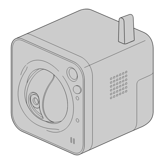
BL-VT164W
This manual covers the models: BL-VT164 Series (BL-VT164W, BL-VT164, BL-VT164WE, BL-VT164E,
BL-VT164WU, BL-VT164U, BL-VT164WBR) and BL-VP100 Series (BL-VP104W, BL-VP104, BL-VP101,
BL-VP104WE, BL-VP104E, BL-VP101E, BL-VP104WU, BL-VP104U, BL-VP101U, BL-VP104WBR).
Before attempting to connect or operate this product, please read these instructions carefully and save this
manual for future use.
The model number is abbreviated in some descriptions in this manual.
Operating Instructions
Network Camera
BL-VT164 Series
Model No.
BL-VP100 Series
BL-VP104W
Advertisement
Table of Contents

Related Manuals for Panasonic BL-VT164WBR


Summary of Contents for Panasonic BL-VT164WBR
- Page 1 BL-VP104W This manual covers the models: BL-VT164 Series (BL-VT164W, BL-VT164, BL-VT164WE, BL-VT164E, BL-VT164WU, BL-VT164U, BL-VT164WBR) and BL-VP100 Series (BL-VP104W, BL-VP104, BL-VP101, BL-VP104WE, BL-VP104E, BL-VP101E, BL-VP104WU, BL-VP104U, BL-VP101U, BL-VP104WBR). Before attempting to connect or operate this product, please read these instructions carefully and save this manual for future use.
- Page 2 About the user manuals There are 2 sets of operating instructions for the BL-VT164W, BL-VT164, BL-VP104W, BL-VP104, BL-VP101 (P model), BL-VT164WE, BL-VT164E, BL-VP104WE, BL-VP104E, BL-VP101E (E model), BL-VT164WU, BL-VT164U, BL-VP104WU, BL-VP104U, BL-VP101U (U model), BL-VT164WBR, BL-VP104WBR (BR model) as follows. •...
- Page 3 Preface Viewer software It is necessary to install the viewer software “Network Camera View 4S” to display images on a PC. This software can be installed directly from the camera or by selecting the [Install] button next to [Viewer Software] on the menu of the CD-ROM provided, and then following the on-screen instructions. IMPORTANT •...
-
Page 4: Table Of Contents
Table of Contents Table of Contents 1 Monitor images on a PC ................7 Monitor images from a single camera ................7 About the “Live” page (BL-VT164W/BL-VT164) ............10 About the “Live” page (BL-VP104W/BL-VP104/BL-VP101) .........15 Monitor images from multiple cameras ................18 2 Monitor images on a cellular phone/mobile terminal ......19 Monitor images on a cellular phone ................19 Monitor images on a mobile terminal ................22 3 Action at an alarm occurrence ..............30... - Page 5 Configure the VMD settings [VMD area] ...............84 11.7 Configuration of the settings relating to the E-mail notification [Notification] ..87 11.8 Configure the settings relating to Panasonic alarm protocol [Notification] .....88 12 Configure the setting relating to the image recognition [Advanced func.] .......................91 12.1 Configure the settings relating to the XML notification [XML notification] ....91...
- Page 6 Installing Panasonic “IP Setting Software” ..............162 20.3 Installing the manuals ....................163 20.4 Installing the Viewer software ..................163 20.5 Configure the network settings of the camera using the Panasonic “IP Setting Software” ........................164 21 About the displayed system log ............166 22 Troubleshooting ...................170 Operating Instructions...
-
Page 7: Monitor Images On A Pc
The following are descriptions of how to monitor images from the camera on a PC. 1.1 Monitor images from a single camera Start up the web browser. Enter the IP address designated using the Panasonic “IP Setting Software” in the address box of the browser. •... - Page 8 1 Monitor images on a PC Press the [Enter] key on the keyboard. → The window with the user name and password entry fields will be displayed. Enter the user name and the password. The default user name and password are as follows. User name: admin Password: 12345 Operating Instructions...
- Page 9 1 Monitor images on a PC Click the [OK] button. → The “Live” page will be displayed. Refer to : page 10, VT164W VT164W VT164 VT164 VP104W VP104W VP104 VP104 : page 15 for further information about the “Live” page. VP101 VP101 When “Off”...
-
Page 10: About The "Live" Page (Bl-Vt164W/Bl-Vt164)
1 Monitor images on a PC 1.2 About the “Live” page (BL-VT164W/BL-VT164) [select language] pull-down menu The camera’s display language can be selected. The default language can be set in the [Language] in the [Basic] settings. (®page 39) [Setup] button Displays the setup menu. - Page 11 1 Monitor images on a PC [VGA] The letters “VGA” will turn green and images in the main area will be displayed in VGA size. [QVGA] The letters “QVGA” will turn green and images in the main area will be displayed in QVGA size.
- Page 12 1 Monitor images on a PC • Preset map-shot: Eight thumbnail images of the preset position 1-8 (®page 65) will be displayed orderly on a newly displayed window. When a thumbnail image is clicked, the camera moves to the respective position and live images will be displayed on the “Live” page. Note •...
- Page 13 1 Monitor images on a PC Snap shot button Click this button to take a picture (a still picture). The picture will be displayed on a newly opened window. When right-clicking on the displayed image, the pop-up menu will be displayed. It is possible to save the image on the PC by selecting “Save”...
- Page 14 1 Monitor images on a PC Note • When operated by a lower access level user, images displayed on the screen may be changed temporarily. This does not affect operation of the camera. • When the mouse is dragged to move the camera beyond its operable range, the camera will move to the requested direction and will stop at the end of the operable range.
-
Page 15: About The "Live" Page (Bl-Vp104W/Bl-Vp104/Bl-Vp101)
1 Monitor images on a PC 1.3 About the “Live” page (BL-VP104W/BL-VP104/ BL-VP101) [select language] pull-down menu The camera’s display language can be selected. The default language can be set in the [Language] in the [Basic] settings. (®page 39) [Setup] button Displays the setup menu. - Page 16 1 Monitor images on a PC [QVGA] The letters “QVGA” will turn green and images in the main area will be displayed in QVGA size. [640x360] The letters “640x360” will turn green and images in the main area will be displayed in 640 x 360 (pixels).
- Page 17 1 Monitor images on a PC Note • The following setting may be necessary when using Windows 7 or Windows Vista. Click “Internet Options” on the Tools menu of Internet Explorer, and then click the [Security] tab. Select “Trusted Sites”, and click “Sites”. Register the camera address on the “Website” in the “Trusted Sites”...
-
Page 18: Monitor Images From Multiple Cameras
When displaying images on a 4-screen, panning, tilting and zooming operations become available only for images from cameras with Pan/Tilt/Zoom functions. Refer to our website (P/E/U model: http://security.panasonic.com/pss/security/support/info.html, BR model: http://www.panasonic.com.br/netcam) for further information about the compatible cameras and their versions. •... -
Page 19: Monitor Images On A Cellular Phone/Mobile Terminal
2 Monitor images on a cellular phone/mobile terminal 2 Monitor images on a cellular phone/mobile terminal 2.1 Monitor images on a cellular phone It is possible to connect to the camera using a cellular phone via the Internet and monitor images (JPEG only) from the camera on the screen of the cellular phone. - Page 20 2 Monitor images on a cellular phone/mobile terminal Access to “http://IP address/mobile” or “http://Host name registered in the DDNS server/mobile” using a cellular phone. → Images from the camera will be displayed. Operating Instructions...
- Page 21 2 Monitor images on a cellular phone/mobile terminal Functions Outline of functions A Pan/tilt Controls the camera direction. The camera will pan or tilt to each direction by pressing the corresponding dial key. VT164W VT164W VT164 VT164 B Zooming control It is possible to perform zooming operations of the camera by pressing “*”...
-
Page 22: Monitor Images On A Mobile Terminal
– Android™ mobile terminals Only JPEG images can be viewed from standard Android mobile terminal browsers. For further information about compatible devices, refer to our website (P/E/U model: http://security.panasonic.com/pss/security/support/info.html, BR model: http://www.panasonic.com.br/netcam). IMPORTANT • When the authentication window is displayed, enter the user name and password. The default user name and password are as follows. - Page 23 2 Monitor images on a cellular phone/mobile terminal Access to “http://IP address/cam” or “http://Host name registered in the DDNS server/cam” using a mobile terminal. → Images from the camera will be displayed. Live images area Displays images from the camera. Operation buttons area When functions are selected in the function selection area D, buttons to operate those functions are displayed.
- Page 24 2 Monitor images on a cellular phone/mobile terminal Click the button of the function that you want to operate. Pan/Tilt VT164W VT164W VT164 VT164 Preset VT164W VT164W VT164 VT164 Resolution control AUX control VT164W VT164W VT164 VT164 Privacy Mode control VT164W VT164W VT164...
- Page 25 2 Monitor images on a cellular phone/mobile terminal Pan/Tilt VT164W VT164W VT164 VT164 Press the button to display the buttons used to operate pan/tilt on the screen. The pan/tilt can be adjusted in each direction with the , and buttons. Preset VT164W VT164W...
- Page 26 2 Monitor images on a cellular phone/mobile terminal Resolution control Press the button to display the buttons used to select the resolution on the screen. The resolution can be changed by selecting a resolution setting from the buttons. • Image in the aspect ratio of “4:3” VT164W VT164W VT164...
- Page 27 2 Monitor images on a cellular phone/mobile terminal AUX control VT164W VT164W VT164 VT164 Press the button to display the buttons used to operate the AUX output on the screen. The AUX output terminals can be controlled with the buttons. This function is only displayed when [Terminal 3] is set to [AUX output] on the settings menu.
- Page 28 2 Monitor images on a cellular phone/mobile terminal Privacy Mode control VT164W VT164W VT164 VT164 Press the button to display the buttons used to operate the privacy mode on the screen. The privacy mode can be enabled and disabled with the buttons.
- Page 29 2 Monitor images on a cellular phone/mobile terminal Zoom display VT164W VT164W VT164 VT164 The camera’s zoom can be operated with the , and buttons. Note • You can change the image size displayed on the mobile terminal by accessing the following addresses. –...
-
Page 30: Action At An Alarm Occurrence
VMD alarm: When motion is detected in the set VMD area, the alarm action will be performed. *VMD stands for “Video Motion Detection”. • Command alarm: When a Panasonic alarm protocol is received from the connected device via a network, the alarm action will be performed. 3.2 Action at an alarm occurrence Display the alarm occurrence indication button on the “Live”... - Page 31 When “On” is selected for “Panasonic alarm protocol”, the connected Panasonic device will be notified that the camera is in the alarm state. The settings for Panasonic alarm protocol can be configured in the Panasonic alarm protocol section of the [Notification] tab of the [Alarm] page. (®page 88)
-
Page 32: Transmit Images Onto An Ftp Server
4 Transmit images onto an FTP server 4 Transmit images onto an FTP server Images can be transmitted to an FTP server. By configuring the following settings, transmission of images captured at an alarm occurrence or captured at a designated interval to an FTP server will become available. IMPORTANT •... -
Page 33: About The Network Security
5 About the network security 5 About the network security 5.1 Equipped security functions The following security functions are featured in this camera. Access restrictions by the host authentication and the user authentication It is possible to restrict users from accessing the camera by setting the host authentication and/or the user authentication to “On”. -
Page 34: Display The Setup Menu From A Pc
6 Display the setup menu from a PC 6 Display the setup menu from a PC The settings of the camera can be configured on the setup menu. IMPORTANT • The setup menu is only operable by users whose access level is “1. Administrator”. Refer to page 94 for how to configure the access level. -
Page 35: How To Operate The Setup Menu
6 Display the setup menu from a PC 6.2 How to operate the setup menu Menu buttons Setup page Click the desired button in the frame on the left of the window to display the respective setup menu. When there are tabs at the top of the “Setup” page displayed in the frame on the right of the window, click the desired tab to display and configure the setting items relating to the name of the tab. - Page 36 6 Display the setup menu from a PC The edited settings in field A will not be applied unless the [Set] button (B) below field (A) is clicked. In the same manner as above, click the [Set] button (D) below field C when completing the setting items in field C.
-
Page 37: About The Setup Menu Window
6 Display the setup menu from a PC 6.3 About the setup menu window [Setup] button Display the “Setup” page. [Live] button Display the “Live” page. [Basic] button Displays the “Basic” page. The basic settings such as time and date and camera title can be configured on the “Basic”... - Page 38 6 Display the setup menu from a PC [Advanced func.] button Displays the “Advanced func.” page. The setting relating to the XML notification, destinations of information about the face detection and the settings relating to the face detection can be configured on the “Advanced func.”...
-
Page 39: Configure The Basic Settings Of The Camera [Basic]
7 Configure the basic settings of the camera [Basic] 7 Configure the basic settings of the camera [Basic] The basic settings such as camera title, time and date, etc. can be configured on the “Basic” page. (®page 34, page 35) [Camera title] Enter the title of the camera. - Page 40 7 Configure the basic settings of the camera [Basic] IMPORTANT • Depending on the conditions such as the ambient temperature and operating period, the configured time & date may not be accurate. • Use an NTP server when the more accurate time & date setting is required for the system operation. (®page 101) [Time display format] Select the time display format from “24h”, “12h”...
- Page 41 7 Configure the basic settings of the camera [Basic] • Available characters: 0-9, A-Z and the following marks. ! " # $ % & ' ( ) * + , - . / : ; = ? • Default: None (blank) [OSD] - [Position] Select the position where the time and date and a character string to be displayed on the image of the “Live”...
- Page 42 7 Configure the basic settings of the camera [Basic] Operation status Indicator status Blinks orange ® Lights off During the initialization Port forwarding error caused by the UPnP function Blinks orange (in 2 seconds intervals (on for 1 second / off for 1 second)) Trouble happening on the camera Blinks red...
- Page 43 7 Configure the basic settings of the camera [Basic] IMPORTANT • It is impossible to display images and to receive/transmit audio between the camera and the PC when the viewer software “Network Camera View 4S” is not installed on the PC. •...
-
Page 44: Configure The Internet Settings [Internet]
By selecting “Viewnetcam.com” and clicking the [Set] button, the registration window for “Viewnetcam.com” will be displayed in a newly opened window. Follow the on-screen instructions to register with “Viewnetcam.com”. Refer to the “Viewnetcam.com” website (P/E/U model: http://www.viewnetcam.com/, BR model: http://www.panasonic.com.br/netcam) for further information about the service. • Default: Off Note •... - Page 45 8 Configure the Internet settings [Internet] [Recommended network setting for internet] The recommended settings for connecting to the Internet are performed here. By clicking the [Set] button, a dialog displaying how the following settings will change is displayed. Click the [OK] button after checking the settings to change the settings to the displayed values. –...
-
Page 46: Configure The Settings Relating To Images And Audio [Image/Audio] (Bl-Vt164W/Bl-Vt164)/ Configure The Settings Relating To Images [Image] (Bl-Vp104W/Bl-Vp104/Bl-Vp101)
9 Configure the settings relating to images and audio [Image/Audio] (BL-VT164W/BL-VT164)/ Configure the settings relating to images [Image] (BL-VP104W/BL-VP104/BL-VP101) 9 Configure the settings relating to images and audio [Image/Audio] (BL-VT164W/BL-VT164)/ Configure the settings relating to images [Image] (BL-VP104W/BL-VP104/BL-VP101) VT164W VT164W VT164 VT164 The settings relating to JPEG and H.264 images such as the settings of image quality, audio, etc. -
Page 47: Configure The Settings Relating To Jpeg Images [Jpeg/H.264]
9 Configure the settings relating to images and audio [Image/Audio] (BL-VT164W/BL-VT164)/ Configure the settings relating to images [Image] (BL-VP104W/BL-VP104/BL-VP101) 9.2 Configure the settings relating to JPEG images [JPEG/H.264] Click the [JPEG/H.264] tab on the “Image/Audio” page. (®page 34, page 35) JPEG Configure the settings such as “Refresh interval (JPEG)*”, “Image capture size”... - Page 48 9 Configure the settings relating to images and audio [Image/Audio] (BL-VT164W/BL-VT164)/ Configure the settings relating to images [Image] (BL-VP104W/BL-VP104/BL-VP101) VP101 VP101 320x180/ 640x360 • Default: 640x360 /VGA VT164W VT164W VT164 VT164 VP104W VP104W VP104 VP104 VP101 VP101 [Image quality] Select the image quality of JPEG images displayed initially on the “Live” page. •...
-
Page 49: Configure The Settings Relating To H.264 Images [Jpeg/H.264]
9 Configure the settings relating to images and audio [Image/Audio] (BL-VT164W/BL-VT164)/ Configure the settings relating to images [Image] (BL-VP104W/BL-VP104/BL-VP101) 9.3 Configure the settings relating to H.264 images [JPEG/H.264] Click the [JPEG/H.264] tab on the “Image/Audio” page. (®page 34, page 35) Operating Instructions... - Page 50 9 Configure the settings relating to images and audio [Image/Audio] (BL-VT164W/BL-VT164)/ Configure the settings relating to images [Image] (BL-VP104W/BL-VP104/BL-VP101) Configure the settings relating to H.264 image such as “Max bit rate (per client)”, “Image capture size”, “Image quality”, etc. in this section. Refer to page 47 for the settings relating to JPEG images. Operating Instructions...
- Page 51 9 Configure the settings relating to images and audio [Image/Audio] (BL-VT164W/BL-VT164)/ Configure the settings relating to images [Image] (BL-VP104W/BL-VP104/BL-VP101) H.264(1)/H.264(2) [H.264 transmission] Select “On” or “Off” to determine whether or not to transmit H.264 images. • On: Transmits H.264 images. •...
- Page 52 9 Configure the settings relating to images and audio [Image/Audio] (BL-VT164W/BL-VT164)/ Configure the settings relating to images [Image] (BL-VP104W/BL-VP104/BL-VP101) [Transmission priority] Select a transmission priority for H.264 images from the following. • Constant bit rate: H.264 images will be transmitted with the bit rate selected for “Max bit rate (per client)*”.
- Page 53 9 Configure the settings relating to images and audio [Image/Audio] (BL-VT164W/BL-VT164)/ Configure the settings relating to images [Image] (BL-VP104W/BL-VP104/BL-VP101) [Refresh interval] Select an interval (I-frame interval; 0.2 - 5 seconds) to refresh the displayed H.264 images. If using under a network environment with frequent error occurrences, shorten the refresh interval for H.264 to diminish image distortions.
- Page 54 9 Configure the settings relating to images and audio [Image/Audio] (BL-VT164W/BL-VT164)/ Configure the settings relating to images [Image] (BL-VP104W/BL-VP104/BL-VP101) Note • When audio is transmitted from the unit, the port number to be used will be the multicast port number plus “1000”.
-
Page 55: Configure The Settings Relating To The Camera Operations [Cam. Function] (Bl-Vt164W/Bl-Vt164)
9 Configure the settings relating to images and audio [Image/Audio] (BL-VT164W/BL-VT164)/ Configure the settings relating to images [Image] (BL-VP104W/BL-VP104/BL-VP101) 9.4 Configure the settings relating to the camera operations [Cam. Function] (BL-VT164W/BL-VT164) Click the [Cam. Function] tab on the “Image/Audio” page. (®page 34, page 35) Configure the settings relating to camera operations. - Page 56 9 Configure the settings relating to images and audio [Image/Audio] (BL-VT164W/BL-VT164)/ Configure the settings relating to images [Image] (BL-VP104W/BL-VP104/BL-VP101) • On: A still image will be held on the screen until the camera has moved to the preset position. • Off: Images from the camera will be displayed even when the camera is moving to the preset position.
-
Page 57: (Bl-Vt164W/Bl-Vt164)/ Configure The Settings Relating To Image Adjust, Extra Zoom, And Privacy Zone [Image/Privacy] (Bl-Vp104W/Bl-Vp104/Bl-Vp101)
9 Configure the settings relating to images and audio [Image/Audio] (BL-VT164W/BL-VT164)/ Configure the settings relating to images [Image] (BL-VP104W/BL-VP104/BL-VP101) 9.5 Configure the settings relating to images and the preset positions [Image/Position] (BL-VT164W/ BL-VT164)/ Configure the settings relating to image adjust, extra zoom, and privacy zone [Image/Privacy] (BL-VP104W/BL-VP104/BL-VP101) VT164W VT164W... -
Page 58: Configure The Settings Relating To Image Quality ("Image Adjust" Setup Menu)
9 Configure the settings relating to images and audio [Image/Audio] (BL-VT164W/BL-VT164)/ Configure the settings relating to images [Image] (BL-VP104W/BL-VP104/BL-VP101) [Privacy zone] Click the [Setup>>] button to display the setup menu that can configure the settings relating to the privacy zone. The setup menu will be displayed in a newly opened window. (®page 68, page 70) 9.5.1 Configure the settings relating to image quality (“Image adjust”... - Page 59 9 Configure the settings relating to images and audio [Image/Audio] (BL-VT164W/BL-VT164)/ Configure the settings relating to images [Image] (BL-VP104W/BL-VP104/BL-VP101) [Adaptive black stretch] Select “On” or “Off” to determine whether or not to activate the darkness compensation function. The darkness compensation function can make darker parts of images brighter by digital image processing. •...
- Page 60 9 Configure the settings relating to images and audio [Image/Audio] (BL-VT164W/BL-VT164)/ Configure the settings relating to images [Image] (BL-VP104W/BL-VP104/BL-VP101) [Back light compensation (BLC)] Select “On” or “Off” to determine whether or not to activate the back light compensation (BLC) function. The back light compensation function can compensate back light by setting mask areas on brighter parts of images.
- Page 61 9 Configure the settings relating to images and audio [Image/Audio] (BL-VT164W/BL-VT164)/ Configure the settings relating to images [Image] (BL-VP104W/BL-VP104/BL-VP101) • Off: Images will be captured with the fixed gain level. • Default: On(High) [Auto slow shutter] The electronic sensitivity enhancement (sensitivity up) can be carried out by adjusting the storage time of the sensor.
-
Page 62: Set Mask Areas
9 Configure the settings relating to images and audio [Image/Audio] (BL-VT164W/BL-VT164)/ Configure the settings relating to images [Image] (BL-VP104W/BL-VP104/BL-VP101) Click the [Reset] button to reset the color to the default. • Default: 128 [Blue gain] Adjust the blue color of images. When the cursor is moved in the “+”... - Page 63 9 Configure the settings relating to images and audio [Image/Audio] (BL-VT164W/BL-VT164)/ Configure the settings relating to images [Image] (BL-VP104W/BL-VP104/BL-VP101) Display the “Image adjust” setup menu. (®page 57) Click the [Start] button of “Mask area”. → : Borders will appear and the image displayed on the [Image/Position] tab will be VT164W VT164W VT164...
- Page 64 9 Configure the settings relating to images and audio [Image/Audio] (BL-VT164W/BL-VT164)/ Configure the settings relating to images [Image] (BL-VP104W/BL-VP104/BL-VP101) Note VP101 VP101 • “Mask area” can be set only when “4:3” is selected for “Aspect ratio”. If the “Aspect ratio” is changed to “16:9”...
-
Page 65: Configure The Settings Relating To The Preset Positions ("Preset Position" Setup Menu) (Bl-Vt164W/Bl-Vt164)
9 Configure the settings relating to images and audio [Image/Audio] (BL-VT164W/BL-VT164)/ Configure the settings relating to images [Image] (BL-VP104W/BL-VP104/BL-VP101) Image in the aspect ratio of “16:9” Areas where the image is not displayed when “4:3” is selected for the aspect ratio Image in the aspect ratio of “4:3”... -
Page 66: Register The Preset Positions
9 Configure the settings relating to images and audio [Image/Audio] (BL-VT164W/BL-VT164)/ Configure the settings relating to images [Image] (BL-VP104W/BL-VP104/BL-VP101) IMPORTANT • When the zoom factor is 1.5x or more, the setting of the preset positions will become unavailable. Note • Depending on the environment (such as when the temperature is below 5°... - Page 67 9 Configure the settings relating to images and audio [Image/Audio] (BL-VT164W/BL-VT164)/ Configure the settings relating to images [Image] (BL-VP104W/BL-VP104/BL-VP101) To display the preset ID on the “Live” page, select “On” for “Preset ID” and enter the desired position title to be displayed. Click the [Set] button.
-
Page 68: Adjust The Angular Field Of View Using The Extra Zoom Function (Bl-Vp104W/Bl-Vp104)
9 Configure the settings relating to images and audio [Image/Audio] (BL-VT164W/BL-VT164)/ Configure the settings relating to images [Image] (BL-VP104W/BL-VP104/BL-VP101) [Set] button Registers the preset positions. [Delete] button Deletes the preset position specified by the position number. [Close] button Click this button to close the “Preset position” setup menu. 9.5.4 Adjust the angular field of view using the extra zoom function (BL-VP104W/BL-VP104) Click the [Setup>>] button of “Extra zoom”... - Page 69 9 Configure the settings relating to images and audio [Image/Audio] (BL-VT164W/BL-VT164)/ Configure the settings relating to images [Image] (BL-VP104W/BL-VP104/BL-VP101) • Depending on the panning/tilting direction (especially when the tilting degree is 45° - 90°) and the zooming factor, the area set as the privacy zone may become visible. Make sure that each of the set privacy zone is not visible after setting it.
-
Page 70: Configure The Settings Relating To The Privacy Zone ("Privacy Zone" Setup Menu) (Bl-Vp104W/Bl-Vp104/Bl-Vp101)
9 Configure the settings relating to images and audio [Image/Audio] (BL-VT164W/BL-VT164)/ Configure the settings relating to images [Image] (BL-VP104W/BL-VP104/BL-VP101) Note • Set the privacy zone larger than the size of an object to be hidden. • Panning, tilting and zooming operations can also be carried out on the [Image/Position] tab. •... - Page 71 9 Configure the settings relating to images and audio [Image/Audio] (BL-VT164W/BL-VT164)/ Configure the settings relating to images [Image] (BL-VP104W/BL-VP104/BL-VP101) • Gray: The privacy zones will be displayed in gray. • Off: Does not display the privacy zones. • Default: Off Note •...
-
Page 72: Configure The Settings Relating To Audio [Audio] (Bl-Vt164W/Bl-Vt164)
9 Configure the settings relating to images and audio [Image/Audio] (BL-VT164W/BL-VT164)/ Configure the settings relating to images [Image] (BL-VP104W/BL-VP104/BL-VP101) 9.6 Configure the settings relating to audio [Audio] (BL-VT164W/BL-VT164) Click the [Audio] tab on the “Image/Audio” page. (®page 34, page 35) The settings relating to audio can be configured on this page. - Page 73 9 Configure the settings relating to images and audio [Image/Audio] (BL-VT164W/BL-VT164)/ Configure the settings relating to images [Image] (BL-VP104W/BL-VP104/BL-VP101) Note • G.711 is available only when “Mic input” is selected for “Audio transmission/reception”. [Audio bit rate] Select “16kbps” or “32kbps” for the audio bit rate used to transmit/receive audio data. •...
- Page 74 9 Configure the settings relating to images and audio [Image/Audio] (BL-VT164W/BL-VT164)/ Configure the settings relating to images [Image] (BL-VP104W/BL-VP104/BL-VP101) [Audio output port (PC to Camera)] Enter the transmission port number (the port number on the camera used to receive audio data transmitted from the PC).
-
Page 75: Configure The Multi-Screen Settings [Multi-Screen]
10 Configure the multi-screen settings [Multi-screen] 10 Configure the multi-screen settings [Multi-screen] The cameras from which images are to be displayed on a multi-screen can be registered on the “Multi-screen” page. (®page 34, page 35) [IP address] Enter the IP address or the host name of the camera to be used for the multi-screen. 4 cameras can be registered as a group and up to 4 groups (16 cameras) can be registered. - Page 76 (®page 119) • “Network Camera Recorder with Viewer Software Lite” which supports live monitoring and recording images from multiple cameras is available. For further information, refer to our website (P/E/U model: http://security.panasonic.com/pss/security/support/info.html, BR model: http://www.panasonic.com.br/netcam). Note •...
-
Page 77: Configure The Alarm Settings [Alarm]
11 Configure the alarm settings [Alarm] 11 Configure the alarm settings [Alarm] The settings relating to alarm occurrences such as settings for the alarm action at an alarm occurrence, the VMD area settings, and the alarm occurrence notification can be configured on this page. The “Alarm”... - Page 78 Select “On” or “Off” to determine whether or not to receive the command alarm. The command alarm is the function that provides notification of a Panasonic protocol alarm from the other cameras. When “On” is selected, alarm actions will be performed between multiple cameras.
-
Page 79: Configure The Settings Relating To The Camera Action On Alarm Occurrence [Alarm] (Bl-Vt164W/Bl-Vt164)
11 Configure the alarm settings [Alarm] [Originating port number] Select a port number to be used to receive the command alarm. • Available range: 1-65535 • Default: 8181 The following port numbers are unavailable since they are already in use. 20, 21, 23, 25, 42, 53, 67, 68, 69, 80, 110, 123, 161, 162, 443, 554, 995, 10669, 10670, 59000-61000 11.2 Configure the settings relating to the camera action on alarm occurrence [Alarm] (BL-VT164W/... -
Page 80: Configure The Settings Relating To The Alarm Image [Alarm]
11 Configure the alarm settings [Alarm] [Body heat sensor] Select an action to be taken when a body heat sensor is detected from the following. • Off: Does not take any action even when a body heat sensor is detected. •... - Page 81 11 Configure the alarm settings [Alarm] Alarm image [FTP >>] When “FTP >>” is clicked, the [FTP] tab of the “Server” page will be displayed. (®page 100) [Alarm image FTP transmission] Select “On” or “Off” to determine whether or not to transmit the alarm image to the FTP server. •...
-
Page 82: Configure The Settings Relating To The Alarm Output Terminal [Alarm] (Bl-Vt164W/Bl-Vt164)
11 Configure the alarm settings [Alarm] [Image compression rate upon alarm detection] Select “On” or “Off” to determine whether or not to change the image quality of “Quality1” (®page 47) upon alarm detection. • On: Images will be transmitted with the image quality selected for “Image quality upon alarm detection”. •... -
Page 83: Change The Aux Name [Alarm] (Bl-Vt164W/Bl-Vt164)
11 Configure the alarm settings [Alarm] • Close: The alarm output terminal will close when outputting the alarm signals. (Normally open) • Default: Close Note • When “Open” is selected, the alarm signal will be output for about 20 seconds when the power of the unit is turned on. -
Page 84: Configure The Vmd Settings [Vmd Area]
11 Configure the alarm settings [Alarm] 11.6 Configure the VMD settings [VMD area] Click the [VMD area] tab on the “Alarm” page. (®page 34, page 35) The video motion detection areas can be set on this page. VT164W VT164W VT164 VT164 The VMD areas can be set up to 4 areas for each preset position (maximum 64 preset positions). - Page 85 Select “On” or “Off” to determine whether or not to add VMD information to superimposed image data. The VMD information can be searched by some Panasonic network disk recorders. Refer to the operating instructions of the connected devices for further information about the functions and settings.
- Page 86 [Area No. notification] When “Panasonic alarm protocol notification >>” is clicked, the [Notification] tab of the “Alarm” page will be displayed. (®page 88) Set the video motion detection area by dragging the mouse on the screen.
-
Page 87: Configuration Of The Settings Relating To The E-Mail Notification [Notification]
11 Configure the alarm settings [Alarm] Click the [Set] button after completing the settings. IMPORTANT • The setting will not be applied unless the [Set] button is clicked. To invalidate the VMD area, click the [Set] button after selecting “Off” for “Status” of the VMD area to be invalidated. -
Page 88: Configure The Settings Relating To Panasonic Alarm Protocol [Notification]
Available number of characters: 0 - 50 characters [E-mail body] Enter the E-mail body. • Available number of characters: 0 - 200 characters 11.8 Configure the settings relating to Panasonic alarm protocol [Notification] Click the [Notification] tab on the “Alarm” page. (®page 34, page 35) Operating Instructions... - Page 89 The settings relating to Panasonic alarm protocol can be configured in this section. Panasonic alarm protocol notification [Panasonic alarm protocol] Select “On” or “Off” to determine whether or not to provide notification by Panasonic alarm protocol according to the settings for the “Alarm” and “Diag.” checkboxes of “Destination of notification” below. –...
- Page 90 Default: 2 Destination of notification [Address 1] - [Address 8] Enter the destination IP address or host name of the Panasonic alarm protocol from the following. Up to 8 destination server addresses can be registered. • [Alarm] checkbox: When the checkbox is selected, the Panasonic alarm notification will be provided upon an alarm occurrence.
-
Page 91: Configure The Setting Relating To The Image Recognition [Advanced Func.]
IMPORTANT • To use the “XML notification” and “Face detection” functions, you need to install the extension software. For further information, refer to our website (http://security.panasonic.com/pss/security/kms/). 12.1 Configure the settings relating to the XML notification [XML notification] Click the [XML notification] tab on the “Advanced func.” page. - Page 92 12 Configure the setting relating to the image recognition [Advanced func.] XML notification [XML notification] Select “On” or “Off” to determine whether or not to notify face detection information using XML. • Default: Off [Notification data] Select the type of data notification. Select one of the following. •...
-
Page 93: Configuration Of The Settings Relating To The Face Detection [Face Detection]
12 Configure the setting relating to the image recognition [Advanced func.] 12.2 Configuration of the settings relating to the face detection [Face detection] Click the [Face detection] tab on the “Advanced func.” page. The settings relating to displaying the frame to be used for the face detection and the settings relating to the face detection information attached to the image can be configured. -
Page 94: Configure The Settings Relating To The Authentication [User Mng.]
13 Configure the settings relating to the authentication [User mng.] 13 Configure the settings relating to the authentication [User mng.] The settings relating to the authentication such as users and PCs restrictions for accessing the camera with a PC or cellular phone/mobile terminal can be configured on the “User mng.” page. The “User mng.”... -
Page 95: Configure The Settings Relating To The Host Authentication [Host Auth.]
13 Configure the settings relating to the authentication [User mng.] Note • When the [Authentication] setting has been changed, close the web browser, and then access the camera again. [User name] Enter a user name. • Available number of characters: 1 - 32 characters •... -
Page 96: Configure The Settings Relating To The Priority Stream [System]
13 Configure the settings relating to the authentication [User mng.] The restriction settings of PCs (IP address) from accessing the camera can be configured on this page. [Host auth.] Select “On” or “Off” to determine whether or not to authenticate the host. •... - Page 97 13 Configure the settings relating to the authentication [User mng.] The description below is the configuration of the priority stream that can transmit images without deteriorating the image quality and refresh interval even when multiple users access concurrently. Priority stream [Activation] Select “On”...
- Page 98 13 Configure the settings relating to the authentication [User mng.] [Image capture size] Select the image capture size from the following. This setting is validated only when “JPEG” is selected for “Stream type”. When “4:3” is selected for “Aspect ratio” VT164W VT164W VT164...
-
Page 99: Configure The Settings Of The Servers [Server]
14 Configure the settings of the servers [Server] 14 Configure the settings of the servers [Server] The settings relating to the E-mail server, the FTP server and the NTP server can be configured on this page. The “Server” page has 3 tabs; the [E-mail] tab, the [FTP] tab and the [NTP] tab. 14.1 Configure the settings relating to the E-mail server [E-mail] Click the [E-mail] tab on the “Server”... -
Page 100: Configure The Settings Relating To The Ftp Server [Ftp]
14 Configure the settings of the servers [Server] IMPORTANT • When entering the host name for “SMTP server address” or “POP server address”, it is necessary to configure the DNS settings on the [Network] tab of the “Network” page. (®page 104) [Authentication] •... -
Page 101: Configure The Settings Relating To The Ntp Server [Ntp]
14 Configure the settings of the servers [Server] [FTP server address] Enter the IP address or the host name of the FTP server. • Available number of characters: 1 - 128 characters • Available characters: Alphanumeric characters, the colon (:), the period (.), the underscore (_), and the hyphen (-). - Page 102 14 Configure the settings of the servers [Server] IMPORTANT • Use an NTP server when the more accurate time & date setting is required for the system operation. [Time adjustment] Select the time adjustment method from the following. Time adjusted by the selected method will be used as the standard time of the camera.
- Page 103 14 Configure the settings of the servers [Server] The following port numbers are unavailable since they are already in use. 20, 21, 23, 25, 42, 53, 67, 68, 69, 80, 110, 161, 162, 443, 995, 10669, 10670 [Time adjustment interval] Select an interval (1 - 24 hours: in 1 hour intervals) of synchronization with the NTP server.
-
Page 104: Configuring The Network Settings [Network]
15 Configuring the network settings [Network] 15 Configuring the network settings [Network] The network settings and the settings relating to DDNS (Dynamic DNS) and SNMP (Simple Network management Protocol) can be configured on the “Network” page. The “Network” page has 4 tabs; the [Network] tab, the [DDNS] tab, the [SNMP] tab and the [FTP img. trans.] tab. - Page 105 15 Configuring the network settings [Network] IPv4 network [Network Settings] Select the method of how to configure the IP address from the following. • Static: The IP address is configured by entering manually on “IP address(IPv4)”. • DHCP: The IP address is configured using the DHCP function. •...
- Page 106 15 Configuring the network settings [Network] • Default: Auto(Advanced) Note • When “Auto(AutoIP)” is selected and the IP address cannot be obtained from the DHCP server, an IP address not used in the same network will be searched within 169.254.1.0 - 169.254.254.255. [IP address(IPv4)] When not using the DHCP function, enter the IP address of the camera.
- Page 107 15 Configuring the network settings [Network] Note • When connecting to the manually configured IPv6 address beyond the router, use an IPv6 compatible router and turn on the automatic IPv6 address assignment function. In this case, it is necessary to configure IPv6 address including prefix information provided from the IPv6 compatible router.
- Page 108 15 Configuring the network settings [Network] UPnP This camera support UPnP (Universal Plug and Play). By using the UPnP function, it becomes possible to configure the following automatically. • Configuration of the port forwarding function of the router (However, a router supporting UPnP is required.) This configuration is useful when accessing the camera via the Internet or from a cellular phone/mobile terminal.
- Page 109 15 Configuring the network settings [Network] [CRT key generate] CRT key (SSL encryption key) used for the HTTPS protocol is generated. To generate the CRT key, click the [Execute] button to display “CRT key generate” dialog box. [Self-signed Certificate - Generate] The camera itself generates the security certificate used for the HTTPS protocol.
- Page 110 “JPEG” on the [JPEG/H.264] tab or set “Image quality setting” of “JPEG” lower. [Easy IP Setup accommodate period] Select “20min” or “Unlimited” to determine how long the network setting operation using the Panasonic “IP Setting Software” can be allowed. •...
- Page 111 15 Configuring the network settings [Network] • To access the camera via the Internet by connecting the camera to a router, it is necessary to assign a respective HTTP port number for each camera and address translation by using the port forwarding function of the router.
-
Page 112: Configure The Https Settings
15 Configuring the network settings [Network] 15.2 Configure the HTTPS settings Click the [Network] tab on the “Network” page. (®page 34, page 35) The settings relating to the HTTPS protocol that can enhance the network security by encrypting the access to cameras on this page. -
Page 113: Generation Of The Crt Key (Ssl Encryption Key)
15 Configuring the network settings [Network] Note • To use the server certificate, you need to apply for the approval and the issue of server certificate by • Either of the self-signed certificate or the server certificate is available. If both of them are installed, the server certificate will be used prior to the self-signed certificate. -
Page 114: Generation Of The Self-Signed Certificate (Security Certificate)
15 Configuring the network settings [Network] key. When the [Apply] button is clicked on the “Previous CRT key” dialog box, it is possible to replace the current CRT key with the previous one. 15.2.2 Generation of the self-signed certificate (security certificate) IMPORTANT •... - Page 115 15 Configuring the network settings [Network] Item Description Available number of characters [Organizational Enter the unit name of the organization. 64 characters Unit] (Omission is OK.) [CRT key] Displays the key size and generation time & date of the current key. Note •...
-
Page 116: Generation Of Csr (Certificate Signing Request)
15 Configuring the network settings [Network] • When the [Delete] button is clicked, the generated self-signed certificate (security certificate) will be deleted. • When “HTTPS” is selected for “Connection”, it is impossible to delete the self-signed certificate. 15.2.3 Generation of CSR (Certificate Signing Request) IMPORTANT •... -
Page 117: Installation Of The Server Certificate
15 Configuring the network settings [Network] Item Description Available number of characters [CRT key] Displays the key size and generation time & date of the current key. Note • To use the server certificate, follow the requests from the CA about the information to be entered. •... -
Page 118: Configuration Of The Connection Protocol
15 Configuring the network settings [Network] • When the [Confirm] button is clicked, the registered information of the installed server certificate will be displayed in the “CA Certificate - Confirm” dialog box. (Only “Organizational Unit” will be displayed with an asterisk (*).) •... -
Page 119: Access The Camera Using The Https Protocol
15 Configuring the network settings [Network] In advance, install the root certificate and intermediate certificate on the browser in use. Follow the instructions of CA for how to obtain and install these certificates. • When the camera is accessed using the HTTPS protocol, the refresh interval and frame rate of images may be lower. - Page 120 15 Configuring the network settings [Network] • When the camera access is open to the Internet, enter the address name or host name to access via the Internet for “Common Name”. In this case, the security alert window will be displayed each time the camera is locally accessed, even if the security certificate is installed.
- Page 121 15 Configuring the network settings [Network] Click “Certificate Error” over the URL, and click “View certificates”. Operating Instructions...
- Page 122 15 Configuring the network settings [Network] Click “Install Certificate...”. Note • If [Install Certificate...] is not displayed, close Internet Explorer once, and select [Run as Administrator] to launch Internet Explorer again. Click [Start] ® [All Programs] ® right click [Internet Explorer] ®...
- Page 123 15 Configuring the network settings [Network] Click “Next” displayed on “Certificate Import Wizard”. Select “Place all certificates in the following store”, and click “Browse...”. Operating Instructions...
- Page 124 15 Configuring the network settings [Network] Select “Trusted Root Certificate Authorities”, and click “OK”. Click “Next”. Operating Instructions...
- Page 125 15 Configuring the network settings [Network] Click “Finish”. Click “Yes”. → When the import is successfully completed, the screen “The import was successful.” will be displayed. Operating Instructions...
- Page 126 15 Configuring the network settings [Network] Click “OK”. → When the browser is restarted after the certificate is imported, “Certificate Error” will not be displayed. OS: Windows XP, Web browser: When using Internet Explorer 6 Access the camera using the HTTPS protocol. Click “View Certificate”.
- Page 127 15 Configuring the network settings [Network] Click “Install Certificate...”. Click “Next >” according to the procedures displayed on the displayed on “Certificate Import Wizard”. Operating Instructions...
- Page 128 15 Configuring the network settings [Network] Click “Finish”. Operating Instructions...
-
Page 129: Configure The Settings Relating To Ddns [Ddns]
“Viewnetcam.com” service. Note • “Viewnetcam.com” is a Dynamic DNS service designed for use with Panasonic Network Cameras. Refer to the “Viewnetcam.com” website (P/E/U model: http://www.viewnetcam.com/, BR model: http://www.panasonic.com.br/netcam) for further information about the service. About DDNS services (IPv4/IPv6) By using a DDNS service, it becomes possible to view camera images via the Internet. -
Page 130: Configuration Of The Ddns Service (Example Of The "Viewnetcam.com" Service)
Enrollment in a domain name service is required even when using the IPv6 connection. Refer to the “Viewnetcam.com” website (P/E/U model: http://www.viewnetcam.com/, BR model: http://www.panasonic.com.br/netcam) for further information about the service. • Static IP address service (such as a service offered by a contracted provider) In this service, global addresses are static (not changed). -
Page 131: When Using The "Viewnetcam.com" Service
15 Configuring the network settings [Network] Global address is obtained via the URL (domain name). By entering the URL (including the domain name) on the web browser when accessing the camera via the Internet, the DNS server identifies the registered global address of router (or camera). Access using the current global address The identified global address is used for accessing the router (or camera) to monitor images. -
Page 132: Procedure To Register Information For The "Viewnetcam.com" Service
“Personal(Camera) URL” is displayed. It may take up to about 30 minutes until the URL of the registered camera is validated. • To cancel the enrollment in the “Viewnetcam.com” service, access the “Viewnetcam.com” website (P/ E/U model: http://www.viewnetcam.com/, BR model: http://www.panasonic.com.br/netcam) later. Operating Instructions... -
Page 133: Checking The Information Registered For The "Viewnetcam.com" Service
15 Configuring the network settings [Network] • When “Expired” is displayed in the URL of “Viewnetcam.com” in the viewnetcam settings page or the status page, restart the camera after registering the “Viewnetcam.com” service. After restarting the camera, check that the registered URL is displayed in the URL of “Viewnetcam.com” of [Status] - [Viewnetcam.com] on the “Maintenance”... -
Page 134: When Using "Dynamic Dns Update(Dhcp)
15 Configuring the network settings [Network] 15.4.6 When using “Dynamic DNS Update(DHCP)” [Host name] Enter the host name to be used for the Dynamic DNS Update service. • Available number of characters: 3 - 250 characters Enter in the form of “(host name). (domain name)”. •... -
Page 135: Configure The Settings Relating To The Ftp Periodic Image Transmission
15 Configuring the network settings [Network] • Available number of characters: 0 - 32 characters • Default: None (blank) [Location] Enter the name of the location where the camera is installed. • Available number of characters: 0 - 32 characters •... - Page 136 15 Configuring the network settings [Network] [FTP periodic image transmission] Select “On” or “Off” to determine whether or not to transmit images using the FTP periodic image transmission function. When “On” is selected, it is necessary to configure the settings of the FTP server. (®page 100) •...
-
Page 137: Configure The Schedule Settings Of The Ftp Periodic Image Transmission
15 Configuring the network settings [Network] 15.7 Configure the schedule settings of the FTP periodic image transmission [FTP img. trans.] Click the [FTP img. trans.] tab on the “Network” page. (®page 34, page 35) The schedule settings of the FTP periodic image transmission can be configured in this section. Refer to page 135 for further information about the settings relating to the FTP periodic image transmission. -
Page 138: How To Delete The Set Schedule
15 Configuring the network settings [Network] Click the [Set] button after completing the settings. → The result will be displayed at the bottom of the window. 15.7.2 How to delete the set schedule Uncheck the check box of the set day of the week. Operating Instructions... - Page 139 15 Configuring the network settings [Network] Click the [Set] button after completing the settings. → The schedule of the selected day of the week is deleted. Operating Instructions...
-
Page 140: Use The Camera On A Wireless Lan [Wireless] (Bl-Vt164W/Bl-Vp104W)
16 Use the camera on a wireless LAN [Wireless] (BL-VT164W/BL-VP104W) 16 Use the camera on a wireless LAN [Wireless] (BL-VT164W/BL-VP104W) Wireless network settings for connecting the camera to a wireless router or other wireless device can be configured on the “Wireless” page. The “Wireless”... - Page 141 16 Use the camera on a wireless LAN [Wireless] (BL-VT164W/BL-VP104W) The wireless settings can be manually configured to the camera in this section, and the camera can be connected to the wireless network. Check the wireless router's setting information. • Check the SSID and wireless security settings configured to your wireless router, and whether MAC address filtering is activated or deactivated.
- Page 142 16 Use the camera on a wireless LAN [Wireless] (BL-VT164W/BL-VP104W) • Default: 802.11n/b/g [ShortGI enabled] Set each item of the [Wireless: Encryption settings] in accordance to the encryption method used. WEP method WPA-PSK (TKIP), WPA-PSK (AES), WPA-PSK (TKIP/AES), WPA2-PSK (TKIP), WPA2-PSK (AES), WPA2-PSK (TKIP/AES), or WPA/WPA2-mixedmode PSK method [Encryption method] Select the encryption method for the data to be transmitted.
- Page 143 16 Use the camera on a wireless LAN [Wireless] (BL-VT164W/BL-VP104W) • 5 alphanumeric characters: 64bit Example: 012yz • 13 alphanumeric characters: 128bit Example: 0123456uvwxyz • Available number of characters: 10 or 26 characters (10 hex characters: 64bit/26 hex characters: 128bit)/5 or 13 characters (5 alphanumeric characters: 64bit/13 alphanumeric characters: 128bit) •...
-
Page 144: Connecting The Camera To A Wireless Lan With Wps (Automatic Settings) [Basic]
16 Use the camera on a wireless LAN [Wireless] (BL-VT164W/BL-VP104W) • Depending on the network environment and the wireless devices used (2.4 GHz cordless telephones/faxes or other wireless LAN devices), transmission speeds may become slower. 16.2 Connecting the camera to a wireless LAN with WPS (automatic settings) [Basic] First, confirm that “Enable”... - Page 145 16 Use the camera on a wireless LAN [Wireless] (BL-VT164W/BL-VP104W) Turn on the camera without connecting the LAN cable to enable the wireless settings. → After the initial pan/tilt operations are performed, the POWER indicator stops blinking orange and lights orange.
- Page 146 16 Use the camera on a wireless LAN [Wireless] (BL-VT164W/BL-VP104W) Configure [Wi-Fi Protected Setup (WPS)]. – Select “Enable” for “External registration”. (Default: Enable) – Select “Use” for “WPS compliant (PIN method)”. (Default: Not use) – Enter the wireless router's 8 digit PIN code in the “PIN code” field. •...
- Page 147 16 Use the camera on a wireless LAN [Wireless] (BL-VT164W/BL-VP104W) Configure [Wi-Fi Protected Setup (WPS)]. – Select “Enable” for “External registration”. (Default: Enable) – Select “Use” for “WPS compliant (PIN method)”. (Default: Not use) – Click the [Generate] button or [Default] button to set the “PIN code”. •...
-
Page 148: Using The Camera's Wireless Qos [Basic]
16 Use the camera on a wireless LAN [Wireless] (BL-VT164W/BL-VP104W) IMPORTANT If the wireless settings failed to be automatically set with WPS, check the wireless settings for the wireless router and camera in the following manner. Checking wireless settings for the wireless router •... - Page 149 16 Use the camera on a wireless LAN [Wireless] (BL-VT164W/BL-VP104W) Note • The screen is refreshed in 10 seconds intervals periodically to monitor the radio wave status. This may cause the screen to flicker. [Wireless module status] Displays the current status of the wireless module. [Firmware version (Wireless)] Displays the wireless firmware version of the camera.
- Page 150 16 Use the camera on a wireless LAN [Wireless] (BL-VT164W/BL-VP104W) [BSSID] Displays the connected wireless router's MAC address. When a wireless router is not connected, “00-00-00-00-00-00” is displayed. [Authentication method] Displays the authentication method (Open System, WPA-PSK, or WPA2-PSK) in accordance to the currently selected encryption method.
-
Page 151: Configure The Settings Relating To The Schedules [Schedule]
17 Configure the settings relating to the schedules [Schedule] 17 Configure the settings relating to the schedules [Schedule] On the “Schedule” page, it is possible to configure the settings relating to schedules as follows. • Alarm permission (Alarm input will be received only in the specified schedule.) •... - Page 152 17 Configure the settings relating to the schedules [Schedule] Select an action to be assigned to the schedule from “Schedule mode”. “Off” is selected at the default. • Off: No action will be taken for the respective schedule. • Alarm permission: Alarm input (terminal alarm) will be received during the period of the schedule. •...
- Page 153 17 Configure the settings relating to the schedules [Schedule] • Body heat sensor permission : The body heat sensor detection will be active VT164W VT164W VT164 VT164 during the period of the schedule. • Access permission: Users whose access level is set to 2 and 3 on the “User auth.” tab (®page 94) can access the camera only in the period of schedule.
-
Page 154: Maintenance Of The Camera [Maintenance]
18 Maintenance of the camera [Maintenance] 18 Maintenance of the camera [Maintenance] System log check, firmware upgrade, status check and initialization of the setup menu can be performed on this page. The “Maintenance” page has 4 tabs; the [System log] tab, the [Upgrade] tab, [Status] tab and the [Default reset] tab. - Page 155 18 Maintenance of the camera [Maintenance] The current firmware can be checked and upgraded to the latest version on this page. Contact the dealer for further information about the firmware upgrade. [Model no.], [MAC address], [Serial no.], [Firmware version], [IPL version], [HTML version], [IP address(IPv6)], [Viewer software installation counter] Information of each item will be displayed.
-
Page 156: Check The Status [Status]
18 Maintenance of the camera [Maintenance] IMPORTANT • After completing the upgrade, delete temporary internet files. (®page 170) • Upgrade the firmware using a PC in the same subnet as the unit. • Follow the instructions from the dealer when upgrading the firmware. •... -
Page 157: Reset The Settings/Reboot The Camera [Default Reset]
• Refer to our website (P/E/U model: http://security.panasonic.com/pss/security/support/info.html, BR model: http://www.panasonic.com.br/netcam) for further information about the contents of the displayed statuses (relating to the “Viewnetcam.com” service, the UPnP function, or the self check). 18.4 Reset the settings/Reboot the camera [Default reset] Click the [Default reset] tab of the “Maintenance”... - Page 158 18 Maintenance of the camera [Maintenance] The settings and the HTML data of the camera can be initialized and reboot of the camera can be performed on this page. [Reset to the default (Except the network settings)] Click the [Execute] button to reset the settings to the default. Note that the network and wireless settings will not be reset.
-
Page 159: Privacy Mode (Bl-Vt164W/Bl-Vt164)
19 Privacy Mode (BL-VT164W/BL-VT164) 19 Privacy Mode (BL-VT164W/BL-VT164) Privacy mode allows you to protect your privacy by hiding the lens inside the camera, preventing camera images from being seen. When privacy mode is activated: – The POWER indicator turns red so that you can easily see that privacy mode is activated. –... -
Page 160: Configuring The Privacy Mode With The Setup Menu
19 Privacy Mode (BL-VT164W/BL-VT164) 19.2 Configuring the Privacy Mode with the setup menu Click the [Privacy] button in the setup menu. → The lens will be hidden in the top part of the camera and the POWER indicator will light. 19.3 Turning the Privacy Mode off You can turn privacy mode off by: –... -
Page 161: Using The Cd-Rom
Using the supplied CD-ROM, the following actions can be performed. The Panasonic “IP Setting Software” can be installed on the PC. (®page 162) Settings related to the camera's network can be set from the Panasonic “IP Setting Software”. (®page 164) The manuals can be installed on the PC. -
Page 162: Installing Panasonic "Ip Setting Software
20 Using the CD-ROM 20.2 Installing Panasonic “IP Setting Software” On the CD launcher window, click the [Install] button next to [IP Setting Software] to display the Panasonic “IP Setting Software” installation window. Confirm the following settings before starting the installation. -
Page 163: Installing The Manuals
To uninstall the manuals delete the shortcut icon from where you specified it to be installed (the default is on the desktop) during installation and the [Manual] folder from the folder (the default is C: \Panasonic) you specified during installation. 20.4 Installing the Viewer software The Viewer software (Network Camera View 4S) must be installed on the PC in order to display camera images. -
Page 164: Configure The Network Settings Of The Camera Using The Panasonic "Ip Setting Software
This camera cannot be displayed or set with an older version of the “IP Setting Software” (version 2.xx). To start the Panasonic “IP Setting Software”, click the [Run] button next to [IP Setting Software] from the CD launcher menu window, or double-click on the shortcut icon created after installing the software on the •... - Page 165 20 Using the CD-ROM Complete each network setup item and click the [Save] button. • For further information about each setting of the “Network Settings” page, refer to page 104. Note • By unchecking the “Wait for camera restarting.” checkbox, multiple cameras can be continuously configured.
-
Page 166: About The Displayed System Log
21 About the displayed system log 21 About the displayed system log Error indications relating to SMTP Category Indication Description POP3 server error Authentication error. • Entered user name or password may be incorrect. Check if the E-mail settings are configured correctly. - Page 167 21 About the displayed system log Category Indication Description Internal error Undefined error. • An error occurred in the FTP function. Check if the FTP settings are configured correctly. Error indications relating to “Viewnetcam.com” Category Indication Description Viewnetcam.com Failed to resolve the •...
- Page 168 21 About the displayed system log Error indications relating to NTP Category Indication Description Connection error No response from the NTP server. • The IP address of the server may be incorrect. Check if the IP address of the server is configured correctly. •...
- Page 169 21 About the displayed system log Error indications relating to Panasonic alarm protocol notification Category Indication Description Panasonic alarm Failed to find destination of • The IP address of the destination of protocol notification notification. notification may be incorrect. Check if the...
-
Page 170: Troubleshooting
If not, proceed either of the following. – Reboot the camera and change the IP address by using the Panasonic “IP Setting Software” within 20 minutes after the restart. Installation Guide – Reboot the camera while holding down the INITIAL SET button on the camera. - Page 171 22 Troubleshooting Symptom Cause/solution Reference pages Cannot access from the web • Is the same IP address provided to other devices? browser. Are there contradictions between the address and the network subnet to be accessed? When the camera and the PC are connected in the same subnet: Are the IP addresses of the camera and the PC set in a common subnet? Or is “Use Proxy Server”...
- Page 172 Log into the “My Account” page of “Viewnetcam.com” website (P/E/U model: http://www.viewnetcam.com/, BR model: http://www.panasonic.com.br/netcam) to check the information of the registered camera. If the global address is not displayed for the IP address field, access the camera, and register the user information for the “Viewnetcam.com”...
- Page 173 E-mail address may be incorrect. Visit the “Viewnetcam.com” website (P/E/U model: http://www.viewnetcam.com/, BR model: http://www.panasonic.com.br/netcam) to register the correct E-mail address. No image is displayed. • Is the viewer software installed on the PC? Install the viewer software on a PC.
- Page 174 22 Troubleshooting Symptom Cause/solution Reference pages • Is the version of DirectX 9.0c or later? ® Check the version of DirectX as follows. Select “Run...” from the start menu of Windows. Enter “dxdiag” in the displayed dialog box and click the [OK] button. If the version of DirectX is older than 9.0c, upgrade it.
- Page 175 22 Troubleshooting Symptom Cause/solution Reference pages Images are displayed washed • Is the brightness setting set at an appropriate level? VT164W VT164W VT164 VT164 out. Click the [Normal] button of [Brightness]. VP104W VP104W VP104 VP104 : 15 VP101 VP101 Flicker appears on the •...
- Page 176 22 Troubleshooting Symptom Cause/solution Reference pages • The firewall function of the anti-virus software may be filtering the port of the camera. Exclude the port number of the camera from the list of the port numbers to be filtered by the anti-virus software.
- Page 177 22 Troubleshooting Symptom Cause/solution Reference pages Cannot connect to the • Is the camera in an area with no wireless signal, or wireless router is there a concrete wall or other obstructions between the camera and wireless router? Check the [Radio wave status] from [Wireless] - VT164W VT164W VP104W...
- Page 178 Select [Allow]. displayed on the information bar. “This webpage wants to run the following add-on: `WebVideo Module' from `Panasonic System Networks Co.,Ltd.`.” (Internet Explorer The following message is • Click the information bar and select “Install displayed on the information ActiveX Control”.
- Page 179 “Security Warning” window. “This webpage wants to install the following add-on: `nwcv4Ssetup.exe' from `Panasonic System Networks Co.,Ltd.`.” (Internet Explorer An unnecessary status bar or • Click “Internet Options...” under “Tools” of the scroll bar is displayed on the menu bar of Internet Explorer, and then click the pop-up window.
- Page 180 Panasonic System Communications Company of North America, Unit of Panasonic Corporation of North America www.panasonic.com/business/ For customer support, call 1.800.528.6747 Three Panasonic Way, Secaucus, New Jersey 07094 U.S.A. Panasonic Canada Inc. 5770 Ambler Drive, Mississauga, Ontario, L4W 2T3 Canada (905)624-5010 www.panasonic.ca...
Need help?
Do you have a question about the BL-VT164WBR and is the answer not in the manual?
Questions and answers