Table of Contents
Advertisement
Quick Links
Advertisement
Table of Contents

Related Manuals for Summit Mig 140i


Summary of Contents for Summit Mig 140i
- Page 1 Mig 140i INVERTER MIG WELDER 140i FLUX/GAS S U M - 9 0 0 9 4 0 OWNER’S MANUAL WARNING: Read carefully and understand all ASSEMBLY AND OPERATION INSTRUCTIONS before operating. Failure to follow the safety rules and other basic safety precautions may result in serious personal injury.
-
Page 2: Limited Warranty
Limited to the warranty periods below, Summit Racing Equipment will repair or replace the item under warranty that fails due to defects in material and workmanship. Summit Racing Equipment must be notified within 30 days of the failure, so as to provide instructions on how to proceed with the repair of your welder and warranty claim processing. -
Page 3: General Safety Rules
GENERAL SAFETY RULES WARNING: Read and understand all instructions. Failure to follow all instructions listed below may result in serious injury. CAUTION: Do not allow persons to operate or assemble this Flux Core 125 until they have read this manual and have developed a thorough understanding of how the Flux Core 125 works. - Page 4 -Do not allow any body part to come in contact with the welding wire if you are in contact with the material being welded, ground or electrode from another welder. -Do not weld if you are in an awkward position. Always have a secure stance while welding to prevent accidents.
- Page 5 your eyes and skin. Do not look at the welding arc without proper eye protection. -Always use a helmet that covers your full face from the neck to top of head and to the back of each ear. -Use a lens that meets ANSI standards and safety glasses. For welders under 160 Amps output, use a shade 10 lens;...
-
Page 6: Technical Specifications
Electromagnetic Field -Electromagnetic fields can interfere with various electrical and electronic devices such as pacemakers. -Consult your doctor before using any electric arc welder or cutting device -Keep people with pacemakers away from your welding area when welding. -Do not wrap cable around your body while welding. -Wrap MIG gun and ground cable together whenever possible. -
Page 7: Know Your Welder
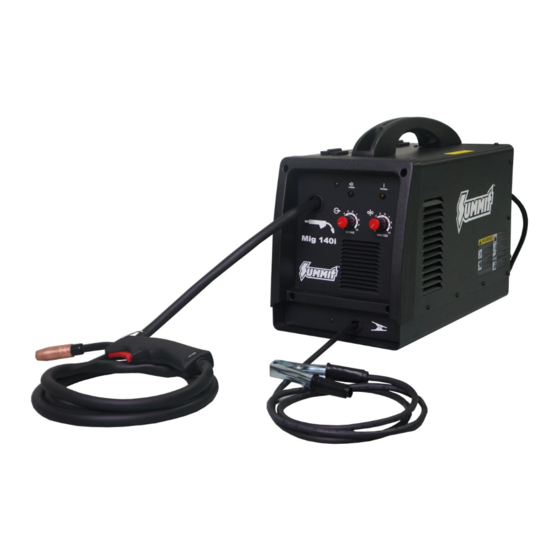
KNOW YOUR WELDER Description The Summit Racing Mig 140i is a portable DC inverter wire feed welder capable of welding with solid wire (with shielding gas) or with flux core wire. This unit uses standard 120VAC, 60 Hz input power on a 20A time delayed fuse or circuit breaker. -
Page 8: Installation
compartment for initial voltage settings. Wire Speed Control Adjustment of the wire feed speed (amperage). . Refer to the “set up” chart inside the wire feed compartment for initial wire feed settings. Ground Cable and Clamp The ground cable and clamp are attached to the work piece to complete the circuit allowing the flow of current needed to weld. - Page 9 3.3 If there is wire already installed in the welder, roll it back onto the wire spool by hand-turning the spool clockwise. Be careful not to all the wire to come out of the rear end of the inlet guide tube without holding onto it or the wire spool will unspool itself.
- Page 10 help to prevent the possibility of the wire jamming inside the gun liner. - Be very careful when removing the welding nozzle. The contact tip on this welder is live whenever the torch trigger is pulled. Make certain POWER is turned OFF. 4.2.1 Remove the nozzle and contact tip from the end of the torch assembly.
- Page 11 when the trigger is released. Readjust the spool tension using the wing nut as necessary to correct for either problem. 4.2.7 With the welder disconnected form the power source, remove the leading end of the wire from the spool. Hold on to it securely, so as not to allow unspooling or tangling of the wire as it will result in tangled wire and feeding problems.
-
Page 12: Gas Installation
5.1 Press the trigger on the torch. 5.2 Turn the drive tension adjustment knob clockwise until the wire seems to feed smoothly without slipping. 6. GAS INSTALLATION Shielding gas cylinders and high pressure cylinders can explode if damaged, so treat them carefully. -
Page 13: Operation
6.5 Open the Gas Bottle Valve on the cylinder of gas. 6.6 Turn the Gas Flow Adjuster on the regulator so that the gas flow rate is set at approximately 20 CFM. Make certain you are reading the correct scale on the gauge. NOTE: Slowly open the cylinder valve by turning it counterclockwise until the cylinder pressure gauge registers on the first gauge of the regulator. -
Page 14: Holding The Torch
speed needs to be closely matched (tuned-in) to the rate at which it is being melted off. Some things that affect wire speed selection are the type and diameter of the wire being used, the heat setting selected, and the welding position to be used. NOTE: - The wire will feed faster without an arc. -
Page 15: Welding Techniques
7.2 Select a heat setting. 7.3 Hold the torch in one hand. Hold the wire just off the work piece. (See HOLDING THE TORCH section if you are uncertain of the angle at which you will be welding). 7.4 Set the wire feed speed based on the thickness of material and the set-up chart on the back side of the wire feeder door. - Page 16 fixed heat setting, the faster the travel speed, the lower the penetration and the lower and narrower the finished weld bead. Likewise, the slower the travel speed, the deeper the penetration and the higher and wider the finished weld bead. 8.2 Types of welding beads As you become more familiar with your new welder and better at laying some simple weld beads, you can begin to try some different weld bead types.
- Page 17 VERTICAL POSITION It is easier for many people to Pull the torch from top to bottom. It can be difficult to prevent the puddle from running downward. Pushing the torch from bottom to top may provide better puddle control and allow slower rates of travel speed to achieve deeper penetration. When vertical welding, angle B (see HOLDING THE TORCH) is usually always kept at zero, but angle A will generally range from 45 to 60 degrees to provide better puddle control.
- Page 18 NOTE: WHEN USING SELF-SHIELDING FLUX-CORE WIRE it is very important to thoroughly chip and brush the slag off each completed weld bead before making another pass or the next pass will be of poor quality. Fillet Weld Joints. Most fillet weld joints, on metals of moderate to heavy thickness, will require multiple pass welds to produce strong joint.
-
Page 19: Spot Welding Instructions
Maintain your Mig 140i. It is recommended that the general condition of any Mig 140i be examined before it is used. Keep your Mig 140i in good repair by adopting a program of conscientious repair and maintenance. Have necessary repairs made by qualified service personnel. -
Page 20: Troubleshooting
TROUBLESHOOTING SYMPTOM POSSIBLE CAUSE CORRECTIVE ACTION Unit Does Not Power Up Unit Is Not Plugged In Plug In Unit Input Power Circuit Breaker Not On Reset Input Power Circuit Breaker The Main Power Switch Is Not Working Replace Main Power Switch Protection Indicator Is On The internal temperature is too high. - Page 21 MAIN CIRCUIT CHART Page of 25...
-
Page 22: Diagram & Parts List
DIAGRAM & PARTS LIST Reference # Part# Description Qty. 185200001 POWER CORD 105400049 POWER CORD STRAIN RELEIF 105200046 POWER SWITCH 105200171 GAS CONNECTOR 185200002 BACK PANEL 105200182 COOLING FAN 105200009 SPOOL HOLDER 105200183 MIDDLE BOARD 105200184 CONTROL PC BOARD 105100075 DOOR HINGE 185200003 ENCLOSURE... - Page 23 Reference # Part# Description Qty. 105200185 MAIN PC BOARD 105200186 POTENTIOMETER 185200005 FRONT PANEL 105200187 OVERLOAD INDICATOR WIRING HARNESS 105200188 POTENTIOMETER KNOB 105200189 GROUND CABLE AND CLAMP 105200042 GROUND CLAMP ONLY 105200190 MIG TORCH 105200191 PLASTIC FRONT PANEL BEZEL 105200192 POWER INDICATOR WIRING HARNESS 105200024 FEET...
- Page 24 Reference # Part# Description Qty. 105200034 FLUX CORE NOZZLE 105200043 .030 CONTACT TIP 105200070 MIG TORCH CONTACT TIP ADAPTER 105200104 TORCH INSULATOR 105200105 TORCH LINER 105200181 MIG TORCH HEAD TUBE 105200062 MIG NOZZLE 21-50 For replacement parts and technical questions contact the technical help line at 1-330-630-3030 Page of 25...
- Page 25 Summit Racing Equipment 1200 Southeast Ave. Tallmadge, OH 44278 www.summitracing.com Made in China Page of 25...
Need help?
Do you have a question about the Mig 140i and is the answer not in the manual?
Questions and answers