Advertisement
Quick Links
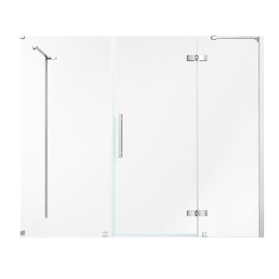
TAMPA CORNER SHOWER
INSTALLATION MANUAL | MANUEL D'INSTALLATION | MANUAL DE INSTALACIÓN
FIXED PANEL, DOOR PANEL, INLINE PANEL & SIDE PANEL
PANNEAU FIXE, PANNEAU DE PORTE, PANNEAU INLINE & PANNEAU LATÉRAL
PANEL FIJO, PANEL DE PUERTA, PANEL INLINE & PANEL LATERAL
Questions, problems, need help?
Call our customer service department at
1-866-839-2888, 8 a.m. - 5 p.m., EST, Monday - Friday
Questions, problèmes ou besoin d'aide?
Contactez notre service à la clientèle au
1-866-839-2888, du lundi au vendredi de 8 h à 17 h HNE.
Preguntas, problemas o necesita ayuda?
Llame a nuestro departamento de servicio al cliente al
1-866-839-2888, 8 am. – 5 pm., HDE, Lunes a Viernes.
P. 1
2022-04-26
www.ovedecors.com | customerservice@ovedecors.com
Advertisement

Related Manuals for OVE Endless Tampa TA2483101


Summary of Contents for OVE Endless Tampa TA2483101
- Page 1 TAMPA CORNER SHOWER INSTALLATION MANUAL | MANUEL D’INSTALLATION | MANUAL DE INSTALACIÓN FIXED PANEL, DOOR PANEL, INLINE PANEL & SIDE PANEL PANNEAU FIXE, PANNEAU DE PORTE, PANNEAU INLINE & PANNEAU LATÉRAL PANEL FIJO, PANEL DE PUERTA, PANEL INLINE & PANEL LATERAL Questions, problems, need help? Call our customer service department at 1-866-839-2888, 8 a.m.
- Page 2 SHOWER DIMENSIONS DIMENSIONS DE LA DOUCHE DIMENSIONES DE LA DUCHA Measurements Rule of Measure Mesures Règle de la mesure Medidas Regla de medida Shower width Distance from the leftmost edge of the shower to the rightmost edge Largeur de la douche Distance de l’extremité...
- Page 3 SHOWER DIMENSIONS DIMENSIONS DE LA DOUCHE DIMENSIONES DE LA DUCHA DIM SP DIM W DIM D DIM FP DIM DP DIM IP DIM O Measures: inch [millimeter] Mesures: pouce [millimètre] Medidas: pulgadas [milímetros] P. 3...
- Page 4 INSTALLATION STRUCTURE OVERVIEW VUE D’ENSEMBLE DE LA STRUCTURE D’INSTALLATION VISIÓN GENERAL DE LA ESTRUCTURA DE INSTALACIÓN 1. Before you start the installation of your product consult the illustration 1 below showing a side-view of the completed installation. 2. Illustration 2 shows the recommended wall structure and measurements for the product installation. NOTE: Customer must follow and comply with the local and national building and plumbing codes.
- Page 5 PACKAGE CONTENT CONTENU DE L’EMBALLAGE CONTENIDO DEL PAQUETE WARNING! Support bar(s) (Part E,F,G) is only needed for panel(s) that is wider than 10 in. AVERTISSEMENT! La ou les barres de support ne sont nécessaires que pour les panneaux dont la largeur est supérieure à 10 po.
- Page 6 PACKAGE CONTENT CONTENU DE L’EMBALLAGE CONTENIDO DEL PAQUETE 1x or 2x 1x or 2x 1x or 2x P. 6...
- Page 7 PACKAGE CONTENT CONTENU DE L’EMBALLAGE CONTENIDO DEL PAQUETE P. 7...
- Page 8 PART LIST LISTE DES PIÈCES LISTA DE PIEZAS PART # DESCRIPTION QUANTITY CODE # DE PIÈCE DESCRIPTION QUANTITÉ CODE PARTE # DESCRIPCIÓN CANTIDAD CÓDIO Oil Rubbed Bronze: 99STR3899-WM Wall track (Fixed Panel) Chrome: 99STR3898-WM Glissière (Panneau Fixe) Satin Nickel: 99STR3900-WM Riel de la pared (Panel Fija) Black: 99STR3899-WM Oil Rubbed Bronze: 99STR3902-WM...
- Page 9 PART LIST LISTE DES PIÈCES LISTA DE PIEZAS PART # DESCRIPTION QUANTITY CODE # DE PIÈCE DESCRIPTION QUANTITÉ CODE PARTE # DESCRIPCIÓN CANTIDAD CÓDIO Gasket stopper Arret de Glissière Parada de ferrocarril Oil Rubbed Bronze: 99SRU3803-WM Wall track gasket Chrome: 99SRU3804-WM Joint d’étanchéité...
- Page 10 SUPPLIED HARDWARE LIST QUINCAILLERIE FOURNIE CONTENIDO DE HARDWARE Wall Anchor Screw Screw Fitting Ancrage mural Raccord Capuchon Tarugo Tornillo Tornillo Accesorio Capuchón ø8x30mm ST5x30mm ST4x12mm 12+4 Bolt Screw Screw Allen key Boulon Clé Allen Perno Tornillo Tornillo Llave Allen M5x20mm ST5x40mm ST4x20mm 2.5mm &...
- Page 11 REVERSIBILITY RÉVERSIBILITÉ REVERSIBILIDAD This instruction is drawn up for a door opening from right to left (see illustration A). For an installation for a door opening from left to right (see illustration B), use the same instructions, but switch around the panels: mirror effect. Utilisez ces instructions pour une ouverture de la porte de droite à...
- Page 12 SAFETY INFORMATION INFORMATION SUR LA SÉCURITÉ INFORMACIÓN DE SEGURIDAD CAUTION Please carefully read the following important safety information before handling or installing this shower. There is a risk of serious injury while handling this product. To minimize these risks, please note: •...
- Page 13 SAFETY NOTICE AVIS DE SÉCURITÉ AVISOS DE SEGURIDAD NOTICE Any modification or alteration from what is specified in this instruction manual will void any and all warranty on this product. The distributor is not responsible for any damage to the unit or personal property caused by improper installation. If you disregard instructional warnings, you will void your warranty and possibly deal with water damage.
- Page 14 WALL TRACK INSTALLATION INSTALLATION DE LA GLISSIÈRE INSTALACIÓN DEL RIEL DE PARED 1.1-1.2. Position the wall track (A) as illustrated. Level the track (A) and mark the track holes positions. 1.3. Remove the track and drill pilot holes in the marked locations with a ø5/16” (8mm) drill bit. 1.4.
- Page 15 WALL TRACK INSTALLATION INSTALLATION DE LA GLISSIÈRE INSTALACIÓN DEL RIEL DE PARED 2.1. Insert the Gasket Stopper (R) into the bottom of the wall track (Q). 2.2-2.3. Position the wall track (Q) as illustrated. Level the track (Q) and mark the track holes positions. 2.4.
- Page 16 WALL TRACK INSTALLATION INSTALLATION DE LA GLISSIÈRE INSTALACIÓN DEL RIEL DE PARED 3.1. Apply a clear silicone to the fixed panel profile (B). 3.2-3.3. Insert the fixed panel (C) into the fixed panel profile (B), making sure the top edge of the fixed panel (C) is flush to the top of the fixed panel profile (B). Allow 24 hours for silicone to dry.
- Page 17 FIXED PANEL INSTALLATION INSTALLATION DU PANNEAU FIXE INSTALACIÓN DEL PANEL FIJO 4.1-4.2. Cut the fixed panel bottom seal strips (K). Install the seal strips (K) at the bottom of the fixed (C). 4.3. Insert the fixed panel (C), into it’s wall track (A). 4.1-4.2.
- Page 18 SIDE PANEL INSTALLATION INSTALLATION DU PANNEAU LATÉRAL INSTALACIÓN DEL PANEL LATERAL 5.1-5.2. Cut the side panel bottom seal strips (V). Install the seal strips (V) at the bottom of the side panel (U). 5.3. Insert the side panel (U), into its wall track (Q). 5.4-5.5.
- Page 19 SHOWER DOOR INSTALLATION INSTALLATION DE LA PORTE DE DOUCHE INSTALACION DE LA PUERTA DE DUCHA 6.1. Disassemble the hinges (J). Be careful not to lose any pieces. 6.2. Install the first part of the hinges (J) onto the fixed panel (C). Ensure that the hinges are tightly screwed in place. Use a ratchet to strongly tighten the blots. 6.3.
- Page 20 SHOWER DOOR INSTALLATION INSTALLATION DE LA PORTE DE DOUCHE INSTALACION DE LA PUERTA DE DUCHA 7.1-7.2. Install the fixed panel vertical seal strip (H) onto the fixed panel (C). The bottom seal was already installed on step 4. 7.3. Using a cutter, cut the surplus parts of the lip of the door bottom seal strip (M). 7.4-7.5.
- Page 21 SHOWER DOOR INSTALLATION INSTALLATION DE LA PORTE DE DOUCHE INSTALACION DE LA PUERTA DE DUCHA 8.1-8.3. Cut the inline panel bottom seal strip (Y) It should be cut so that is it roughly half an inch away from the glass edges and bottom support clamps. Refer to the below drawing for exact measurements.
- Page 22 SHOWER DOOR INSTALLATION INSTALLATION DE LA PORTE DE DOUCHE INSTALACION DE LA PUERTA DE DUCHA 9.1-9.2. Insert the magnetic seal strips (I & W) onto the door panel (D) and the inline panel (X). Adjust the door panel (D) and the inline panel (X) to yield a tight door seal.
- Page 23 SHOWER DOOR INSTALLATION INSTALLATION DE LA PORTE DE DOUCHE INSTALACION DE LA PUERTA DE DUCHA 10.1. Disassemble the clamps (L). 10.2. Place the clamps (L) into the fixed panel (C), inline panel (X) and side panel (U), mark the hole’s place. Remove the clamp and make a hole in the base using ø1/8”(3mm) drill bit.
- Page 24 SHOWER DOOR INSTALLATION INSTALLATION DE LA PORTE DE DOUCHE INSTALACION DE LA PUERTA DE DUCHA 11.1-11.2. Secure the fixed panel (C) by drilling guide holes through the wall track (A) and screwing it in place using fittings (DD), screws (CC) and caps (EE). Measure approximately 3”...
- Page 25 SEALING SCELLAGE SELLADO Ensure that the door closes tightly and opens smoothly. Ensure that there is a firm connection between the fixed panel(s) and the support bar. Apply a clear silicone water sealant around the outside perimeter of any fixed shower components. Allow 24 hours for silicone to dry. Improper application of silicone sealant may cause your shower to leak.
- Page 26 WARNING! The support bar is only required when the glass panel width “D” is larger than 10 in (D > 10 in). If the glass panel width “D” is 10 in or smaller, it is normal that you did not receive a support bar. The installation is complete and you can forgo all subsequent steps.
- Page 27 SUPPORT BAR INSTALLATION INSTALLATION DU BRAS DE SUPPORT INSTALACIÓN DE LA BARRA DE APOYO 13.1. Mount the anchor (E) and the fixed panel brackets (G) onto the support bar (F). 13.2. Fix the anchor (E) to the support bar (F) with the bolts (FF). 13.3.
- Page 28 SUPPORT BAR INSTALLATION INSTALLATION DU BRAS DE SUPPORT INSTALACIÓN DE LA BARRA DE APOYO 14.1. Completely remove the support bars (F). 14.2-14.3. Drill a hole on the center marks with a ø5/16” (8mm) drill bit. If there are no studs located behind the support bar anchor (E), then insert the wall anchors (AA) using a rubber mallet until the wall anchors are flush with the wall.
- Page 29 SUPPORT BAR INSTALLATION INSTALLATION DU BRAS DE SUPPORT INSTALACIÓN DE LA BARRA DE APOYO 15.1. The anchor (E) allows you to adjust the angle between the anchor (E) and the support bar (F). Loose or tighten the bolt of the anchor (E) to make the anchors (E) attach to the wall correctly.
- Page 30 SUPPORT BAR INSTALLATION INSTALLATION DU BRAS DE SUPPORT INSTALACIÓN DE LA BARRA DE APOYO 16.1. Loose the outer side screw (GG) enough to allow for some movement. 16.2. Loose or tighten the bolt of the anchor (E) to adjust the angle of the panel. 16.3-16.5.
- Page 31 MAINTENANCE AND CARE ENTRETIEN ET MAINTENANCE MANTENIMIENTO Y CUIDADO For daily maintenance, use a wet cloth and a soft liquid cleaner on all glass and acrylic surfaces. Doing so will prevent soap or hard water buildups that can etch the glass or acrylic surface over time if left to dry. Never use abrasive cleaners containing some acetone, chlorine or strong bleach, scrapers, metallic brushes, nor other objects or the products which can graze or tarnish surfaces.
- Page 32 LIMITED Product Warranty The DISTRIBUTOR is a distributor of the following Products: • Shower Doors (warranty period 5 years). • Acrylic Surfaces (warranty period 5 years against blistering, cracking or chipping in the acrylic surface). • Acrylic Shell Structure (warranty period 5 years against loss of water through fiberglass laminate of the acrylic body). •...
- Page 33 ANNEX GUIDELINES UTILISATION DE L’ANNEXE USO DEL ANEXO HOW TO USE THE ANNEX TO FIND ADEQUATE DIMENSIONS The dimensions provided in the tables of this ANNEX will vary based on the exact configuration of the shower kit you purchased. Refer to the dimensions fitting for your shower configuration.
- Page 34 ANNEX DIMENSIONS DRAWINGS DESSINS DE DIMENSIONS POUR ANNEXE DIBUJOS DIMENSIONALES DEL ANEXO DIM FP DIM DP DIM IP DIM O DIM SP DIM W DIM D Finished Wall Surface Measure this dimension from the finished wall to the center of your wall track.
- Page 35 ANNEX IMPERIAL MEASUREMENTS (INCHES) ANNEXE MESURES IMPÉRIALES (POUCES) ANEXO MEDIDAS IMPERIALES (PULGADAS) CONFIG BASE TA1311*0* FPB10 (9 3/4in) DPB24 (23 9/16in) IP06 (5 5/8in) SP29 (28 15/16in) 41 5/8 42 13/16 30 3/16 31 1/8 30 3/16 42 3/16 13 3/4 41 13/16 29 13/16 TA1312*0*...
- Page 36 ANNEX IMPERIAL MEASUREMENTS (INCHES) ANNEXE MESURES IMPÉRIALES (POUCES) ANEXO MEDIDAS IMPERIALES (PULGADAS) CONFIG BASE TA1412*0* FPB10 (9 3/4in) DPB30 (29 9/16in) IP06 (5 5/8in) SP31 (30 15/16in) 47 5/8 48 3/4 32 3/16 33 1/8 32 3/16 48 3/16 13 3/4 47 13/16 31 7/8 TA1413*0*...
- Page 37 ANNEX IMPERIAL MEASUREMENTS (INCHES) ANNEXE MESURES IMPÉRIALES (POUCES) ANEXO MEDIDAS IMPERIALES (PULGADAS) CONFIG BASE TA2322*K* FPB24 (23 3/4in) DPB24 (23 9/16in) IP08 (7 5/8in) SP31 (30 15/16in) 60x34x2 3/4in 57 5/8 58 13/16 74 3/4 33 1/8 59 1/16 13 3/4 57 13/16 31 7/8 TA2322*0*...
- Page 38 ANNEX IMPERIAL MEASUREMENTS (INCHES) ANNEXE MESURES IMPÉRIALES (POUCES) ANEXO MEDIDAS IMPERIALES (PULGADAS) CONFIG BASE TA2433*0* FPB24 (23 3/4in) DPB30 (29 9/16in) IP10 (9 5/8in) SP33 (32 15/16in) 65 5/8 66 13/16 34 3/16 35 1/16 34 3/16 66 1/4 13 3/4 65 13/16 33 13/16 TA2441*0*...
- Page 39 ANNEX METRIC MEASUREMENTS (MILLIMETERS) ANNEXE MESURES MÉTRIQUES (MILLIMÈTRES) ANEXO MEDIDAS MÉTRICAS (MILÍMETROS) CONFIG BASE TA1311*0* FPB10 (247mm) DPB24 (599mm) IP06 (143mm) SP29 (735mm) 1057 1087 1829 1829 1072 1062 TA1312*0* FPB10 (247mm) DPB24 (599mm) IP06 (143mm) SP31 (786mm) 1057 1087 1829 1829 1072...
- Page 40 ANNEX METRIC MEASUREMENTS (MILLIMETERS) ANNEXE MESURES MÉTRIQUES (MILLIMÈTRES) ANEXO MEDIDAS MÉTRICAS (MILÍMETROS) CONFIG BASE TA1412*0* FPB10 (247mm) DPB30 (751mm) IP06 (143mm) SP31 (786mm) 1209 1239 1829 1829 1224 1214 TA1413*0* FPB10 (247mm) DPB30 (751mm) IP06 (143mm) SP33 (836mm) 1209 1239 1829 1829 1224...
- Page 41 ANNEX METRIC MEASUREMENTS (MILLIMETERS) ANNEXE MESURES MÉTRIQUES (MILLIMÈTRES) ANEXO MEDIDAS MÉTRICAS (MILÍMETROS) CONFIG BASE TA2322*K* FPB24 (603mm) DPB24 (599mm) IP08 (194mm) SP31 (786mm) 1524x864x70mm 1464 1494 1899 1829 1524 1501 1468 TA2322*0* FPB24 (603mm) DPB24 (599mm) IP08 (194mm) SP31 (786mm) 1464 1494 1829...
- Page 42 ANNEX METRIC MEASUREMENTS (MILLIMETERS) ANNEXE MESURES MÉTRIQUES (MILLIMÈTRES) ANEXO MEDIDAS MÉTRICAS (MILÍMETROS) CONFIG BASE TA2433*0* FPB24 (603mm) DPB30 (751mm) IP10 (245mm) SP33 (836mm) 1667 1697 1829 1829 1682 1672 TA2441*0* FPB24 (603mm) DPB30 (751mm) IP12 (296mm) SP29 (735mm) 1718 1748 1829 1829 1733...
Need help?
Do you have a question about the Endless Tampa TA2483101 and is the answer not in the manual?
Questions and answers
I need the installation manual for OVE Decors TA1342400 Tampa Corner Frameless Hinge Shower Door, 47 5/8 to 48 13/16 in. W x 72 in. H, Black
You can find the installation manual for the OVE Decors Endless Tampa TA2483101 Corner Frameless Hinge Shower Door in the provided documentation labeled "TAMPA CORNER SHOWER INSTALLATION MANUAL."
This answer is automatically generated