Advertisement
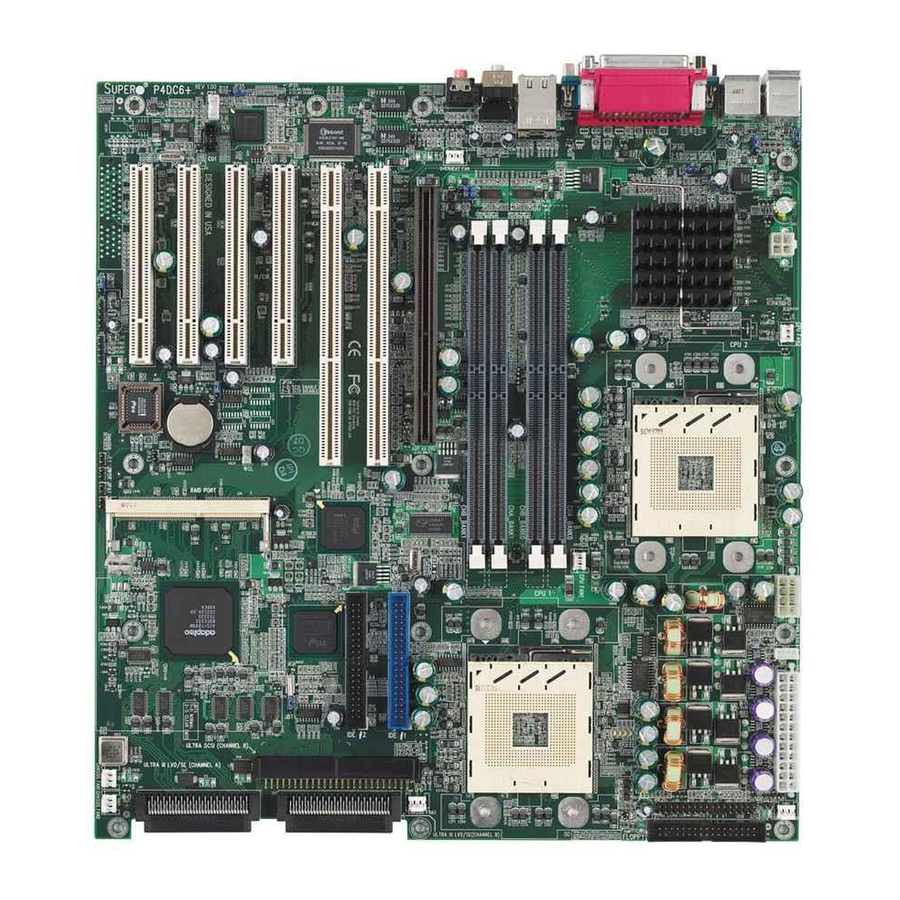
Motherboard Components
6
10
11
12
13
20
1
System Board
2
BIOS
3
RAID Port
4
JWOR
5
JPA1 SCSI Terminator
6
JPA2 SCSI Terminator
7
JP34
8
WOL
9
AIC-7899
10, 11
CH FAN1, CH FAN2
12
Ultra160 LVD SCSI CHA
13
Ultra160 LVD SCSI CHB
14
Ultra SCSI CHB
15
ICH2
16, 17
IDE#1, IDE#2
18
JBT1
Two continuity memory modules must be installed in Bank 1 if only one pair of RAMBUS modules is installed in Bank 0.
*
Front Panel Functions
1
1. 6 SCA Ultra160 hot-swap drive bays
2. 1 slim CD-ROM
3. Floppy drive
4. 1 x 5.25" drive bay
5.
Overheat: Indicates an overheat condition in the system
6.
NIC1: Indicates network activity on LAN1 when flashing
7.
HDD: Indicates IDE channel activity.
8.
Power: Indicates power is being supplied to the system's
power supply units
56
57
58
53
1
52
4
5
51
2
3
7
8
9
19
15
16
17
18
14
30
21
23
24
25
19
P64H
20
CH FAN3
21, 22
CPU#1, CPU#2
23
JF1
24
Floppy
25
JP38
26
CH FAN4
27
ATX Power
28
JP37 Power Fail Signal Conn.
29
J24 (8-pin 12V conn.)
30, 31
CPU FAN1, CPU FAN2
32
J23 (4-pin 12V conn.)
33
JP39
34
JPWAKE
35
JP36
36
MCH
2
3
4
5 6 7 8
55
54
41
50
49
42
48
47
46
45
44
43
36
22
27
29
28
26
37
Mouse and Keyboard Ports
38
2 USB Porta
39
Parallel Port, COM1, COM2
40
LAN
41
AC97' Audio CODEC
42
OH FAN
43,44
Rambus Bank 0
45,46
Rambus Bank
47
AGP Pro Slot
48,49
2 64-bit PCI (66MHz)
50,51,52,53
54
JP35
55
CD1, CD2
56
JP4
57
J20
58
J29
P4DC6+ Quick Reference
Jumper
JBT1
JP2, JP2A1 Manufacturer setting
JPA1, A2
JPA3
JP4
JP35
JP34
JP36
JP38
JP39
JPWAKE
40
38
37
39
35
34
33
32
31
*
1*
4 32-bit PCI (33MHz)
Description
Default Setting
CMOS clear
Pins 1-2 (Normal)
Pins 1-2 (Auto)
SCSI termination
Open (Enabled)
64-bit PCI speed select
Open (66 MHz)
Onboard audio
Pins 1-2 (Enabled)
LAN enable/disable
Pins 1-2 (Enabled)
SCSI enable/disable
Pins 1-2 (Enabled)
Manufacturer setting
Pins 1-2 (Enabled)
Third power supply fail alarm
Open (Disabled)
USB wake up
Pins 1-2 (Enabled)
Keyboard wake up
Pins 1-2 (Disabled)
Advertisement
Table of Contents

Related Manuals for Supermicro P4DC6 Plus


Summary of Contents for Supermicro P4DC6 Plus
- Page 1 Motherboard Components System Board BIOS RAID Port 21, 22 JWOR JPA1 SCSI Terminator JPA2 SCSI Terminator JP34 AIC-7899 10, 11 CH FAN1, CH FAN2 Ultra160 LVD SCSI CHA 30, 31 Ultra160 LVD SCSI CHB Ultra SCSI CHB ICH2 16, 17 IDE#1, IDE#2 JBT1 Two continuity memory modules must be installed in Bank 1 if only one pair of RAMBUS modules is installed in Bank 0.
- Page 2 This is especially critical for 2U dual processor servers with speeds of 1 GHz and above. 1) Only those CPU heatsinks that are provided by Supermicro should be used. 2) Apply a small amount of silicon compound on the CPU's die.
Need help?
Do you have a question about the P4DC6 Plus and is the answer not in the manual?
Questions and answers