Advertisement
Quick Links
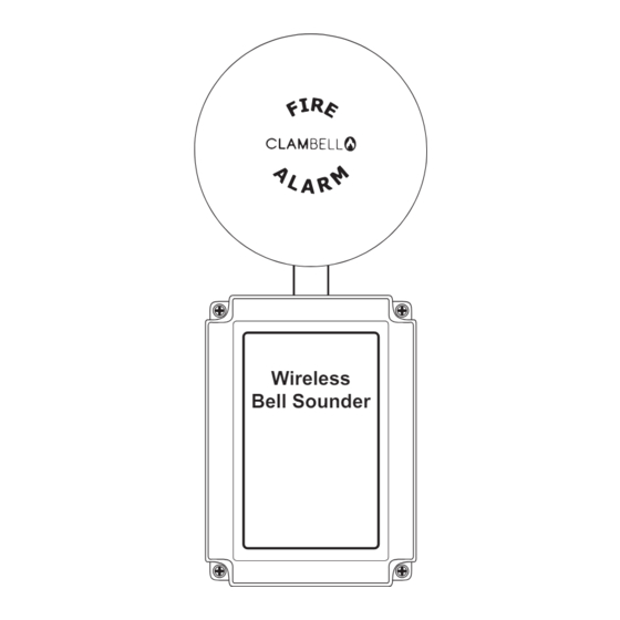
Wireless Bell Sounder
Installation Guide
1 Pre Installation
Installation must conform to applicable local installation
!
codes and should only be installed by a fully trained
competent person.
Ensure that the device is installed as per the site survey.
The use of a non-metallic spacer should be considered if
mounting the device on to a metal surface.
Do NOT Press the Log On button on a pre-programmed device,
as this will cause communication with the Control Panel to be
lost. Should this happen, delete the device from the system
and add it back on.
3 Disassemble Device
Remove the anti-tamper screw (A),
and press the button (B) to open the
gong's hinged cover ...
(B)
(A)
5 Unlock Wireless Module
To unlock the wireless module
from
the
mounting
plate,
insert a 1.5mm Allen key into
the allen key slot and turn
anticlockwise as shown.
©2022 EMS Ltd. All rights reserved
Wireless
Bell Sounder
ATTENTION
OBSERVE PRECAUTIONS
FOR HANDLING
ELECTROSTATIC
SENSITIVE
then unscrew the lid fixing
screws to remove the front lid.
Part No
Product Description
FC-171-003
Wireless Bell Sounder Base
FC-174-002
Wireless Bell Sounder
* Parts 7 and 8 from Components section. See below.
2 Components
1
2
Gong
Gong anti-tamper screw
3
1.5mm Allen key
5
6
Front lid
Wireless module
7
Battery retaining
plate
3
4
4 Fix Device To Wall
Whilst
using
the
mounting template (MK277):
Ensure the device is fitted in the
orientation shown.
DO NOT fit the device on an uneven
surface.
Use all eight circled mounting
positions.
Use suitable fasteners and fixings.
6 Power Device
Remove the wireless module and battery retaining plate. Note:
when removing cables, DO NOT use excessive force.
When fitting / replacing batteries; observe correct polarity,
using only specified batteries.
Connect the power jumper across the PIN header.
SIZE AA
Page 1 of 2
Only*
1
4
4x lid fixing screws
5
7
6
supplied
base
device
unpowered
(pins unlinked)
device
powered
(both pins linked)
Mk276 Iss 4 11/01/2022 AJM
2
Advertisement

Related Manuals for EMS FC-171-003


Summary of Contents for EMS FC-171-003
- Page 1 Connect the power jumper across the PIN header. device SIZE AA unpowered (pins unlinked) device powered (both pins linked) ©2022 EMS Ltd. All rights reserved Page 1 of 2 Mk276 Iss 4 11/01/2022 AJM...
- Page 2 2010 and March 2012. Fire detection and fire alarm systems. Part 25: Components using radio links. Operating Voltage 3.5 to 4.5Vdc European union Hereby, EMS declares that the radio equipment type Current Consumption 0.2 to 300mA directives Wireless Bell Sounder is in compliance with Directive 2014/53/EU.