Advertisement
Quick Links
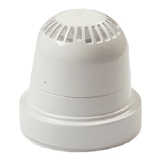
Wireless Sounder / Visual Indicator
Installation Guide
1 Pre installation
Installation must conform to applicable local installation
codes and should only be installed by a fully trained
!
competent person.
Ensure that the device is installed as per the site survey.
The use of a non-metallic spacer should be considered if
mounting the device on to a metal surface.
Do NOT Press the Log On button on a pre-programmed device,
as this will cause communication with the Control Panel to be
lost. Should this happen, delete the device from the system
and add it back on.
This device contains electronics that may be susceptible to
damage from Electrostatic Discharge (ESD). Take appropri-
ate precautions when handling electronic boards.
3 Fix mounting plate
Remove
the
mounting
ANTICLOCKWISE, to release it from the mounting plate.
When wall mounting, ensure the mounting plate is fitted in the
orientation shown.
Use both mounting holes.
Use suitable fasteners and fixings.
5 Optional device locking
To lock the sounder into
the
wireless
module,
remove the cut out section
as shown.
To
unlock
the
device,
insert a 1.5 mm allen key
to depress the locking clip
and turn anticlockwise to
release.
©2021 EMS Ltd. All rights reserved
Example shown:
FC-172-001
FC-171-001
plate
by
turning
the
63 mm
THIS WAY
UP WHEN
WALL
MOUNTING
Cut out section
(shaded area)
Part no
FC-171-001
FC-171-002
FC-172-001
FC-172-002
FC-173-002
FC-173-003
FC-173-004
FC-178-002
FC-178-003
FC-178-004
See the Specification section for compliance information.
2 Components
1
1
Sounder/visual indicator variant
3
Battery retaining plate
4 Power device
Unclip the battery retaining plate from the wireless module.
device
When fitting / replacing batteries; observe correct polarity,
using only specified batteries.
Connect the power jumper across the PIN header.
Once powered, reassemble the device.
6 Configuration
The device's loop address is configured within the user interface's
menu structure.
Refer to the programming manual for full programming details.
FireCell = MK98
Fusion = TSD062
WZM = TSD143
Free to download from
www.emsgroup.co.uk
Page 1 of 2
Product description
White Wireless Sounder Base Only
Red Wireless Sounder Base Only
White Sounder Only
Red Sounder Only
Red Sounder Visual Indicator Only
Amber Sounder Visual Indicator Only
Clear Sounder Visual Indicator Only
Red Visual Indicator Only
Amber Visual Indicator Only
Clear Visual Indicator Only
2
2
4
Mounting plate
SIZE AA
(both pins linked)
TSD047-99 Iss 16 23/11/2021
CPR
[2]
[2]
[1]
[1]
[1]
[1]
[1]
3
4
Wireless module
device
unpowered
(pins unlinked)
device
powered
AJM
Advertisement

Subscribe to Our Youtube Channel
Related Manuals for EMS FireCell FC-171-001


Summary of Contents for EMS FireCell FC-171-001
- Page 1 Fusion = TSD062 insert a 1.5 mm allen key WZM = TSD143 to depress the locking clip and turn anticlockwise to release. Free to download from www.emsgroup.co.uk ©2021 EMS Ltd. All rights reserved Page 1 of 2 TSD047-99 Iss 16 23/11/2021...
- Page 2 Part 25: Components using radio links. Operating frequency 868 MHz European union EMS declares that this device is in compliance with directives Directive 2014/53/EU. The full text of the EU Output transmitter declaration of conformity is available at the following...
Need help?
Do you have a question about the FireCell FC-171-001 and is the answer not in the manual?
Questions and answers