
Related Manuals for PushCorp 0605 Series

Summary of Contents for PushCorp 0605 Series
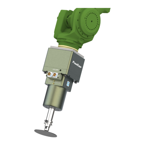
- Page 1 0605 / 1503 Series High Speed Servo Motor Manual ORP, Dallas, Texas February, 2023...
- Page 2 Doing so will damage the motor and power amplifier. All PushCorp, Inc. electrical cables are rated for high twist and flex robotic applications with a minimum cable bending radius specification of 125mm (5 in). Cable damage resulting from failure to abide by this specification will not be covered under warranty.
-
Page 3: Table Of Contents
2.0 GENERAL OVERVIEW..................3 3.0 INSTALLATION & OPERATION................4 3.1 Mounting the spindle motor......................4 3.1.1 Mounting to a PushCorp AFD compliant tool................4 3.1.2 Mounting Directly to a Robot......................6 3.2 Media and Tool Presentation......................6 3.3 Tool and Media Specification......................7 3.3.1 SM Toolholder Specification...................... -
Page 4: Limited Warranty
Dallas, Texas 75218 Shipping Address: 3001 W Kingsley Rd Garland, Texas 75041 Who receives this warranty (purchaser): The original purchaser (other than for purposes of resale) of the PushCorp, Inc. product What products are covered by this warranty: Any PushCorp, Inc. - Page 5 0605 / 1503 Servo Motor Series Manual ORP, Responsibilities of the purchaser under this warranty: A. Deliver or ship the PushCorp, Inc. product or component to PushCorp, Inc. Service Center, Dallas, TX. Freight and insurance costs, if any, must be borne by the purchaser.
-
Page 6: General Overview
This greatly improves reliability by allowing the motor shaft to spin freely and never be subject to any clamping forces. All PushCorp motors use sealed bearings to ensure a long life. The bearings have additional contamination protection from a PushCorp proprietary contact shaft seal. -
Page 7: Installation & Operation
ORP, also cause the O-rings that seal the cooling water channels to fail, possibly filling the motor with water. PushCorp has provided flow through water cooling on the motor to allow high duty cycles without overheating. Simple reliable construction combined with high torque and precision speed controlled servo technology make the PushCorp Servo Motor line a rugged, state-of-the-art tool capable of providing flexible, cost-effective operations. - Page 8 0605 / 1503 Servo Motor Series Manual ORP, Figure 1: Spindle Motor Parallel-Axis Configuration Figure 2: Spindle Motor Perpendicular-Axis Configuration...
-
Page 9: Mounting Directly To A Robot
0605 / 1503 Servo Motor Series Manual ORP, 3.1.2 Mounting Directly to a Robot For some processes compliance and force control are not required. The motor can be mounted directly to the robot. This robotic system is equivalent to a 5-axis machining center with a very large work volume and lower positional accuracy. -
Page 10: Tool And Media Specification
Toolholder can be tailored to any needed configuration to attach to various disk back-up pads, drill bits, router bits, grinding stones, etc. If desired, PushCorp, Inc. can fabricate custom Toolholders, at an additional cost, based on customer supplied drawings and specifications. To prevent interference between the Toolholder and the Collet an 11°... - Page 11 0605 / 1503 Servo Motor Series Manual ORP, 1.55 [39.3] ER COLLET SM MOTOR SHAFT ER COLLET NUT Figure 5: SM Collet Drawing 1.125 [28.58] 0.875 [22.23] 11° END TO SUIT CUSTOMER'S MEDIA TAPER TO MATCH R0.020 [R0.51] MAX. TAPERED HOLDER Ø0.500±0.001 [Ø12.70±0.03] Figure 6: SM Toolholder Drawing...
-
Page 12: Bt30 Toolholder Specification
0605 / 1503 Servo Motor Series Manual ORP, 3.3.3 BT30 Toolholder Specification The STC-BT30 motor is designed to grip a BT30 toolholder. The BT30 toolholder is a standard machine tool style and may be purchased from several sources including, MSC (www.msc.com), and J & L Industrial Supply (www.jlindustrial.com). Customer can also make their own BT30 toolholder to handle special media (See Figure 7 for toolholder dimensions). -
Page 13: Sm Collet Operation
0605 / 1503 Servo Motor Series Manual ORP, 3.4 SM Collet Operation The Collet for the SM motor is tightened and loosened manually. The Motor Shaft must be held using the Motor Shaft Flats, while the Collet Nut is turned, see Figure 11. -
Page 14: Pneumatic Connection
ALL line pressure when unenergized. PushCorp highly recommends the installation of a quick exhaust valve in the Supply Line to the STC; the quick exhaust valve should be mounted as close to the STC unit as possible. - Page 15 NOTE: PushCorp recommends SMC quick exhaust valves, part number AQ-3- 40F-06-00 for 6 mm diameter tubing or part number AQ-3-40F-07-00 for 1/4 inch diameter tubing.
- Page 16 0605 / 1503 Servo Motor Series Manual ORP, Figure 11: 0605/1503 External Features...
-
Page 17: Electrical Connections
The 0605/1503 servo motor has two electrical connections, the Motor Power and Motor Feedback (See Figure 12). If PushCorp supplies the cables and amplifier the tool should be easily connected to the amplifier. If the customer wishes to use their own cables and/or amplifier the pin-outs for the Motor Power and Motor Feedback connectors are shown below in Figure 12. -
Page 18: S724 Servo Amplifier - Default Electrical Connections
0605 / 1503 Servo Motor Series Manual ORP, 3.6.1 S724 Servo Amplifier – Default Electrical Connections This amplifier is already properly configured for a PushCorp spindle. No further configuration is required if the below settings will work for your application. Analog Velocity Mode... -
Page 19: Hall Motor Timing Chart
0605 / 1503 Servo Motor Series Manual ORP, 3.6.2 Hall Motor Timing Chart Figure 13: Hall Motor Input/Output... -
Page 20: Motor Cooling
14, PCI PN PAR03962. In this case the return line is the bottom connection; it is recommended that a flow sensor is installed inline with this port and wired back as part of the control circuit. PushCorp recommends the IFM flow sensor (PN SBG12IF0FRKG). This will ensure the coolant is circulating completely through the motor and back to the cooler. -
Page 21: Monitoring Motor Temperature
Again, it is recommended to constantly monitor the motor temperature during operation to ensure that it does not overheat. In addition, PushCorp recommends that one Miller Coolmate 3 (or equivalent) should be used per motor. -
Page 22: Motor Acceleration/Deceleration
If using the Kollmorgen servo amplifier, the acceleration/deceleration ramp times are preprogrammed by PushCorp into the drive. Should you have any questions or need clarification on if you need to add a ramp to your servo motor control logic contact PushCorp Inc. Technical Support. -
Page 23: Stc Spindle Tool Change
ORP, 3.10 STC Spindle Tool Change PushCorp STC spindles have the ability to switch tool holders out using pneumatic actuation. The STC0605 & STC1503 use a keyless BT30 toolholder, which provides strong holding torque and tool retention. To properly change out a tool, the following steps are recommended to avoid damaging the spindle, toolholder or gripper fingers. - Page 24 0605 / 1503 Servo Motor Series Manual ORP, Figure 16: STC Spindle Tool Change Sequence...
-
Page 25: Technical Specifications
STC-BT30 – N/A Toolholder: SM – Ø0.5 inch (12.7mm) standard STC-BT30 – BT30 toolholder Clamping Supply Air: Dry, Non-lubricated, 90 psi (6.2 bar) Min., 100 psi (6.9 bar) Max. Requires power amplifier and cables. For specific dimensions see www.pushcorp.com for detail drawings. -
Page 26: Preventative Maintenance Schedule
It is highly recommended to adhere to the preventative maintenance schedule in order help extend the longevity of the specified PushCorp, Inc. equipment. Failing to do so could cause a loss in functionality as well as a decrease in product life.
Need help?
Do you have a question about the 0605 Series and is the answer not in the manual?
Questions and answers