
Related Manuals for Spirent GSS7000


Summary of Contents for Spirent GSS7000
- Page 1 GSS7000 SIGNAL GENERATOR USER MANUAL COVERING SPIRENT’S GSS7000 SIGNAL GENERATOR DGP01430AAA Issue:1-11 Date of Issue: 14 March 2019 Document status: OFFICIAL...
- Page 2 PROPRIETARY INFORMATION THE INFORMATION CONTAINED IN THIS DOCUMENT IS THE PROPERTY OF SPIRENT COMMUNICATIONS PLC. EXCEPT AS SPECIFICALLY AUTHORISED IN WRITING BY SPIRENT COMMUNICATIONS PLC, THE HOLDER OF THIS DOCUMENT SHALL KEEP ALL INFORMATION CONTAINED HEREIN CONFIDENTIAL AND SHALL PROTECT SAME IN WHOLE OR IN PART FROM DISCLOSURE AND DISSEMINATION TO ALL THIRD PARTIES TO THE SAME DEGREE IT PROTECTS ITS OWN CONFIDENTIAL INFORMATION.
-
Page 3: Table Of Contents
LED indicators ........................3-8 3.2.4 Model number and serial number ..................3-12 3.2.5 Using dual-output GSS7000-series signal generators as single-output signal generators 3-12 Installing and using the signal generator .................. 3-12 Synchronising from external equipment ................... 3-13 3.4.1 1PPS IN..........................3-13 3.4.2... - Page 4 1-11 DGP01430AAA This page is intentionally blank GSS7000 Signal Generator user manual Contents © 2019 Spirent Communications plc...
-
Page 5: General Details
1-11 General details Spirent reserves the right to supply signal generator elements that may be superficially and visually different to those shown in this document or in an interconnection drawing, but which provide equivalent or better performance. This document includes safety information for safely using Spirent’s GSS7000 signal generators. You must follow all safety instructions detailed in this document before operating your signal generator. -
Page 6: Earth (Ground) Connection
50 to 60 Hz 1.2.5 Fuse rating Spirent fits T5AH 250VAC fuses to the GSS7000 AC power inlet. You must replace fuses with an approved fuse of the same type and rating. The fuse rating is: T: time lag (anti-surge) -
Page 7: Lifting The Signal Generator
Do not block the exhaust ports on the rear panel and ensure you route cables away from the rearpanel exhaust ports. 1.2.9.1 Thermal protection You can fit up to four channel banks to your GSS7000 signal generator. Each channel bank comprises one Signal Generator module and one RF upconverter module. -
Page 8: Dimensions
Remove any accumulated dust using a vacuum cleaner. In the event of dust build-up on the large rear panel exhaust port, Spirent recommends you inspect the heat sink fitted to each Signal Generator card. Dust build-up on these heat sinks could adversely affect the operation of your signal generator, eventually leading to thermal shutdown. -
Page 9: Disposal
1.5 Disposal Spirent simulator products meet the requirements of the European Union (EU) Waste Electrical and Electronic Equipment (WEEE) Directive. The WEEE Directive requires Spirent to label products placed on the EU market after August 2005 with this ‘wheeled bin’ symbol: This symbol indicates the product contains material that presents an environmental concern. - Page 10 1-11 DGP01430AAA This page is intentionally blank GSS7000 Signal Generator user manual General details © 2016-2019 Spirent Communications plc...
-
Page 11: Gss7000 Introduction
DGP01430AAA 1-11 GSS7000 Introduction GSS7000 signal generators are precision signal generators, controlled by one of these versions of Spirent’s PosApp software (your licence determines the version you use): → SimTEST, see reference a) → SimGEN, see reference b), or →... - Page 12 1-11 DGP01430AAA This page is intentionally blank GSS7000 Signal Generator user manual GSS7000 Introduction © Spirent Communications plc 2016-2019...
-
Page 13: Hardware Channels - Gss7000 Signal Generator
For example, the GPS constellation must allocate an equal number of channels to L1, L2 and L5 (where used). These examples show using the <scenario>-Vehicle 1-Antenna 1-Hardware channels-GSS7000 channel usage dialog to assign channels between each constellation in a scenario for a single-output signal generator. - Page 14 This figure shows that reducing the number of Quasi-Zenith channels to nine increases the number of BeiDou channels to 15 (the total channels remain at 64) GSS7000 installed with the maximum four channel banks (supporting up to 64 channels per channel bank, one frequency band per channel bank).
- Page 15 You can easily upgrade your signal generator by installing additional channel banks, up to a maximum of four and installing a new licence file to support additional capability; you do not have to return your signal generator for upgrade. GSS7000 Signal Generator user manual © Spirent Communications plc 2016-2019...
- Page 16 1-11 If you use a dual-output GSS7000 signal generator, assign channels to each RF output using …Antenna 1-Hardware channels and …Antenna 2-Hardware channels. These figures show examples of the GSS7000 channel usage dialogs for RF output 1 and RF output 2:...
-
Page 17: Outline Of Operation
DGP01430AAA 1-11 2.2 Outline of operation These figures are simplified diagrams of the major modules in a single- and dual-output GSS7000 signal generator: Single-output Dual-output Embedded Host, page 2-2, to Power Supply Unit, page 2-6, give top-level descriptions of the modules shown in the diagram above. -
Page 18: Embedded Host
Dispose of used batteries in accordance with local and national environmental regulations The Embedded Host uses a battery to store BIOS settings. Should this battery fail, your GSS7000 signal generator will continue to function as normal. The Embedded Host BIOS battery is not user-replaceable; you must contact... -
Page 19: Rf Combiner
2.2.4 DC power rail indicators DC power rail indicators are only visible with the GSS7000 side covers removed. You must look through the slot in the side casing shown in the figure below (front panel is on the left-hand side) to see... - Page 20 Off - power rail off Digital power rail Green - power rail on Off - power rail off 12V_DIG Digital power rail Green - power rail on Off - power rail off GSS7000 Signal Generator user manual GSS7000 Introduction © 2016-2019 Spirent Communications plc...
-
Page 21: Timer Indicators
1-11 2.2.5 Timer indicators Timer indicators are only visible with the GSS7000 side covers removed. Look through the slot in the side casing shown in the figure below (front panel is on the left-hand side) to see the Timer indicators:... -
Page 22: Power Supply Unit
Internal baffles prevent power supply cooling and exhaust air from mixing with cooling and exhaust air from the signal generator. The power supply fan is independent of the signal generator cooling fans. GSS7000 Signal Generator user manual GSS7000 Introduction © 2016-2019 Spirent Communications plc... -
Page 23: Gss7000 Overview And Installation
IEC60950 GSS7000 signal generators have single, or (optionally) dual, RF Out ports. Each RF Out port is a “composite” output port, with all satellite channels available on this port, together with any signal you apply to the rear panel EXT RF IN port. -
Page 24: Ports
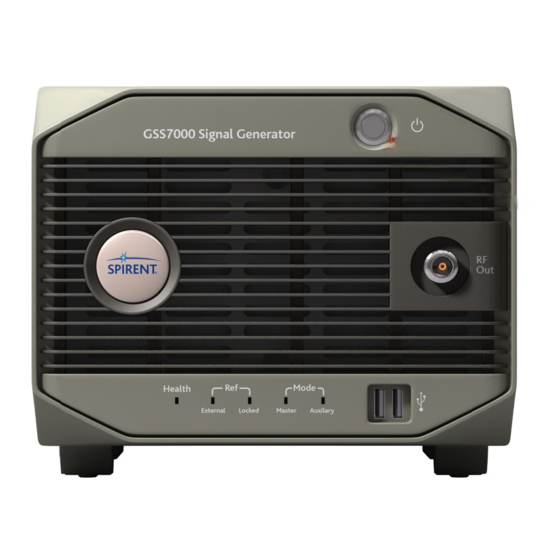
Frequency reference not locked or External reference connected Frequency reference locked White Indicator Status Description Mode - when using a single GSS7000 signal generator Master Single signal generators always run as Master Auxiliary not applicable 3.1.2 Ports Note: The RF Out front panel port is isolated up to 50 Volts (dc) -
Page 25: Rear Panel
You must ensure any connection to a rear panel port is within the SELV limits of IEC60950 This figure shows the rear panel of a GSS7000 signal generator (notice Spirent may not fit all connectors for certain configurations): 3.2.1 Ports... - Page 26 Note: BeiDou users be aware that BeiDou time lags GPS time by 14 seconds, see the chapter “BeiDou constellation editor” of reference a) Connector label Type Description AUX CONT Fischer Currently not in use GSS7000 Signal Generator user manual GSS7000 overview and installation © 2016-2019 Spirent Communications plc...
- Page 27 Note: You can change Timer outputs using SimTEST, reference a). However, certain hardware configurations may become TIMER 2, invalid. If you are in doubt, contact Spirent before changing TIMER 3 Timer outputs. TTL level outputs capable of driving 50 Ohm.
-
Page 28: Usb Port Assignment
USB device. The PosApp USB assign utility starts automatically when Windows boots on the GSS7000 Embedded Host and displays the New USB device connected dialog when you connect a USB device to any GSS7000 USB port: Select Assign for use in Windows or Assign for use in Linux/PosApp engine and then click Apply. - Page 29 USB device. 3.2.2.1 Reset USB port assignment Note: Following the steps in this section will reset the current USB port assignments for all USB ports on the GSS7000 Embedded Host In certain cases, you may need to change your initial USB port assignment. For example, you initially set the USB port...
-
Page 30: Led Indicators
DGP01430AAA 3.2.3 LED indicators Note: In the event of a fault, Spirent recommends you take a photograph of each page, Spirent Global Services may request copies of these photographs to assist in fault-finding. This section describes the twelve, green, LED indicators under the recessed Internal Host port panel. - Page 31 On - 1VA dc supply present Off - PECL_VCC dc supply not present On - PECL_VCC dc supply present Off - DC not OK On - DC OK GSS7000 Signal Generator user manual © 2016-2019 Spirent Communications plc GSS7000 overview and installation...
- Page 32 Currently not in use (permanently set on) Currently not in use (permanently set on) Currently not in use (permanently set on) Currently not in use (permanently set on) GSS7000 Signal Generator user manual 3-10 GSS7000 overview and installation © 2016-2019 Spirent Communications plc...
- Page 33 Currently not in use (permanently set on) Currently not in use (permanently set on) Currently not in use (permanently set on) Currently not in use (permanently set on) GSS7000 Signal Generator user manual 3-11 © 2016-2019 Spirent Communications plc GSS7000 overview and installation...
-
Page 34: Model Number And Serial Number
You can use your dual-output GSS7000 signal generator as a single-output signal generator by: → Removing the terminations Spirent fits to the AUX RF IN 1 port and the HIGH LEVEL 2 port. Store the terminations in a safe place. -
Page 35: Synchronising From External Equipment
Alternatively, you can select Immediate Trigger Mode, which forces the timer to a point just before the one-second rollover and freezes it until your GSS7000 signal generator detects a rising edge on the TRIGGER IN port - the scenario starts running after a short delay. -
Page 36: Trig In - Immediate Mode
= 40 nanoseconds). However, before the simulation starts, there is a delay of six, 10 MHz clock cycles after hold recognizing the trigger, as in this figure: GSS7000 Signal Generator user manual 3-14 GSS7000 overview and installation © 2016-2019 Spirent Communications plc... -
Page 37: Trig In - Delayed Mode
If the rising edge of the signal applied to the rear panel port TRIGGER IN is under 1.1 milliseconds before the 1PPS event, your GSS7000 signal generator will start on the next 1PPS, giving a one second delay: GSS7000 Signal Generator user manual 3-15 ©... - Page 38 1-11 DGP01430AAA This page is intentionally blank GSS7000 Signal Generator user manual 3-16 GSS7000 overview and installation © 2016-2019 Spirent Communications plc...
-
Page 39: Gss7000 Calibration And Service
4.1.1 Sharp edges NOTICE Sharp edges may be present on internal parts of your GSS7000 signal generator Spirent recommends you exercise care when working inside your signal generator Sharp edges are present in the following internal areas of the signal generator: →... - Page 40 1-11 DGP01430AAA This page is intentionally blank GSS7000 Signal Generator user manual GSS7000 calibration and service © 2016-2019 Spirent Communications plc...
-
Page 41: Spirent Global Services
After contacting Spirent Global Services to report a fault, Global Services staff will create a System Report (SR) and copy you with the SR reference number. Spirent Global Services request you use the SR reference number in all correspondence relating to that incident. All responses from Spirent in relation to your incident will contain the SR reference number. - Page 42 Devon TQ4 7QR So far as Spirent Communications plc is aware the contents of this document are correct. However, such contents have been obtained from a variety of sources and Spirent Communications plc can give no warranty or undertaking and make no representation as to their accuracy.
- Page 43 COVERING SPIRENT’S GSS7000 SIGNAL GENERATOR Copyright © 2016 - 2019 Spirent Communications plc The copyright of this publication is the property of Spirent Communications plc. Without the written consent of Spirent Communications plc, given by contract or otherwise, this document must not be copied, reprinted or...
Need help?
Do you have a question about the GSS7000 and is the answer not in the manual?
Questions and answers