Sign In
Upload
Download
Add to my manuals
Delete from my manuals
Share
URL of this page:
HTML Link:
Bookmark this page
Add
Manual will be automatically added to "My Manuals"
Print this page
×
Bookmark added
×
Added to my manuals
Manuals
Brands
KS Manuals
Bicycle Accessories
LEV-Ci
User manual
KS LEV-Ci User Manual
Height adjustable seatpost
Hide thumbs
1
2
3
4
5
6
7
8
9
10
11
12
13
14
15
16
17
18
19
20
21
22
page
of
22
Go
/
22
Bookmarks
Advertisement
Quick Links
Download this manual
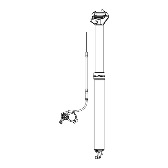
HEIGHT ADJUSTABLE SEATPOST
USER MANUAL
This user manual covers the following models: LEV-Ci, LEV Integra, LEV-Si, e30-i, Crux-i,
eTen-i
1
Table of
Contents
Previous
Page
Next
Page
1
2
3
4
5
Advertisement
Need help?
Do you have a question about the LEV-Ci and is the answer not in the manual?
Ask a question
Questions and answers
Related Manuals for KS LEV-Ci
Bicycle Accessories KS LEV Ci User Manual
Height adjustable seatpost (150 pages)
Bicycle Accessories KS LEV User Manual
Height adjustable seatpost (18 pages)
Bicycle Accessories KS LEV-Si User Manual
Height adjustable seatpost (22 pages)
This manual is also suitable for:
Lev integra
Lev-si
E30-i
Crux-i
Eten-i
Print
Rename the bookmark
Delete bookmark?
Delete from my manuals?
Login
Sign In
OR
Sign in with Facebook
Sign in with Google
Upload manual
Upload from disk
Upload from URL


Need help?
Do you have a question about the LEV-Ci and is the answer not in the manual?
Questions and answers