
Related Manuals for KS LEV


Summary of Contents for KS LEV
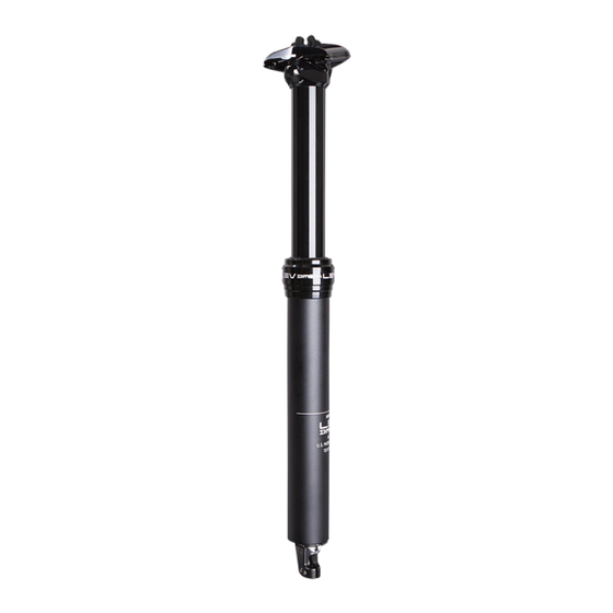
- Page 1 HEIGHT ADJUSTABLE SEATPOST USER MANUAL This user manual covers the following models: LEV, LEV Carbon, LEV DX, and LEV 272...
-
Page 2: Please Read This First
PLEASE READ THIS FIRST Thank you for purchasing a new KS Height Adjustable Seatpost. Your new seatpost is warranted for a period of two years from the date of purchase. The warranty is expressly limited to the repair or replacement of the defective part and is the sole remedy of the warranty. - Page 3 BEFORE YOU INSTALL THE SEATPOST Please be sure your new KS seatpost is designed to fit in your frame. All LEV models are designed to fit either 27.2mm, 30.9mm, 31.6mm, or 34.9mm seat tube inner diameters. Improper fit may cause slippage, faulty performance, injury and may result in void of warranty.
-
Page 4: Seatpost Installation
SEATPOST INSTALLATION SEATPOST ORIENTATION (LEV AND LEV 272) To accomodate all frame styles and cable routing configurations, LEV can be oriented in 20-degree increments as shown below: Rear of Bicycle (LEV DX) (LEV DX & LEV Carbon) (LEV DX) (LEV DX) (LEV DX &... - Page 5 SEATPOST INSTALLATION MINIMUM INSERTION DISTANCE All seat post models must be inserted into the bicycle’s seat tube to cover the minimum insertion line indicated on the seat post. Insufficient insertion of the seat post into the bicycle frame’s seat tube could result in damage to the seat post and/or bicycle and may result in a loss of control...
- Page 6 SADDLE INSTALLATION AFTER SETTING SEATPOST ORIENTATION IN YOUR FRAME Depending on how you have oriented your LEV seatpost within your seat tube, you may need to align your saddle to point forward. To do this, please first remove the two saddle head clamp bolts, spherical nuts, upper and lower floating clamp using a 4mm Hex wrench.
- Page 7 SADDLE INSTALLATION Using a flathead screwdriver, remove the air valve cap from the top end of the stanchion tube. Air Valve Cap At this point, the lower floating clamp cradle and lower clamp body can rotate freely and be correctly oriented to the front of the bicycle.
- Page 8 Head Clamp Bolts 8 N-m 8 N-m See note below See note below Using a 4mm hex wrench, tighten the two head clamp bolts to the maximum torque indicated on your KS dropper post head clamp. Torques may vary by model.
- Page 9 Open the hinged lever clamp and position it in the desired location on your handlebar. Close the clamp and install the pinch bolt. Tighten to a maximum torque of 5 N-m (LEV alloy remote) and 1N-m (LEV Integra polycarbonate remote). Non-hinged...
- Page 10 Your new LEV seatpost includes a 1700mm long cable, 1500mm long cable housing, and an in-line barrel adjuster. Depending on your own requirements, you may need to shorten the cable to minimize excess slack when mounted to your frame. With the remote lever installed on your handlebar, route the cable...
-
Page 11: Cable Installation
CABLE INSTALLATION Hold the free end of the cable and cable housing to LEV’s cable entry point. Mark this length on the cable and cable housing with a marking pen or tape. Using a pair of bicycle cable cutters, trim the cable housing to this measured length. - Page 12 CABLE INSTALLATION CONNECTING THE CABLE TO THE SEATPOST If the cable junction cover is installed, please carefully remove it now. You may need to insert a small (1-2mm) rod such as a paper clip or small Hex wrench to gently lift the end of the cover or if you are adjusting the cable length and the cable is already installed, pull the cable out and lift up.
- Page 13 CABLE INSTALLATION Ensure that the spring is seated fully within the cable junction box. Pull the inner wire and cable housing against the spring until you are able to slide the barbed ferrule into the slotted guide at the base of the cable junction box. Spring Cable Junction Box Ferrule...
- Page 14 CABLE INSTALLATION Push the junction box cap down and the barbed ferrule up to lock it in place. Be careful not to cut or pinch the junction box cover’s o-ring dust seal. If the dust seal is dry or prone to pinching, apply a small amount of grease to help it seat in the junction box.
- Page 15 USING YOUR SEAT POST FOR THE FIRST TIME When using your seat post for the first time, it may be necessary to give the post a firm downward “nudge” to start the initial movement. This is due to the seal’s natural tendency to migrate oil away from the seal surface.
- Page 16 ADJUSTING THE RETURN SPEED NOTE: All LEV models come with suitable pressure for the return spring. Test the return speed of LEV before you make adjustments. Using a flathead screwdriver, remove the air valve cap from the top end of the stanchion tube.
- Page 17 PERIODIC MAINTENANCE Your KS seat post requires periodic service to maintain consistent function. This service should be done at the same interval as a drivetrain cleaning. Please see your local dealer to have this service performed.
- Page 18 Rev. 2014.4...
Need help?
Do you have a question about the LEV and is the answer not in the manual?
Questions and answers