Advertisement
Table of Contents
- 1 Table of Contents
- 2 Warning Decal Placement
- 3 Important Precautions
- 4 Before You Begin
- 5 Part Identification Chart
- 6 Assembly
- 7 How to Use the Treadmill
- 8 Fcc Information
- 9 How to Fold and Move the Treadmill
- 10 Maintenance and Troubleshooting
- 11 Exercise Guidelines
- 12 Part List
- 13 Exploded Drawing
- 14 Ordering Replacement Parts
- 15 Limited Warranty
- Download this manual
proform.com
Model No. PFTL73621.0
Serial No.
Write the serial number in the space
above for reference.
Serial Number
Decal
REGISTER YOUR
PRODUCT
To register your product and
activate your warranty today,
go to my.proform.com.
MEMBER CARE
For service at any time, go to
support.proform.com.
Or call 1-833-680-IFIT
(1-833-680-4348)
Mon.–Fri. 6 a.m.–6 p.m. MT
Sat. 8 a.m.–12 p.m. MT
Please do not contact the store.
CAUTION
Read all precautions and
instructions in this manual before
using this equipment. Keep this
manual for future reference.
USER'S MANUAL
Advertisement
Table of Contents

Related Manuals for Pro-Form POWER T7L


Summary of Contents for Pro-Form POWER T7L
- Page 1 proform.com Model No. PFTL73621.0 USER’S MANUAL Serial No. Write the serial number in the space above for reference. Serial Number Decal REGISTER YOUR PRODUCT To register your product and activate your warranty today, go to my.proform.com. MEMBER CARE For service at any time, go to support.proform.com.
-
Page 2: Table Of Contents
TABLE OF CONTENTS WARNING DECAL PLACEMENT ............. . . 2 IMPORTANT PRECAUTIONS . -
Page 3: Important Precautions
IMPORTANT PRECAUTIONS WARNING: To reduce the risk of burns, fire, electric shock, or injury to persons, read all important precautions and instructions in this manual and all warnings on your treadmill before using your treadmill. ICON assumes no responsibility for personal injury or property damage sus- tained by or through the use of this product. - Page 4 19. Read, understand, and test the emergency able to safely lift 45 lbs. (20 kg) to move the stop procedure before using the treadmill treadmill. (see HOW TO TURN ON THE POWER on page 19). Always wear the clip while using the 26.
- Page 5 STANDARD SERVICE PLANS...
-
Page 6: Before You Begin
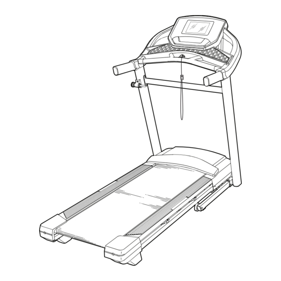
Thank you for selecting the new PROFORM ® reading this manual, please see the front cover of this POWER T7L treadmill. The POWER T7L treadmill manual. To help us assist you, note the product model provides an impressive selection of features designed number and serial number before contacting us. -
Page 7: Part Identification Chart
PART IDENTIFICATION CHART Use the drawings below to identify small parts used for assembly. The number in parentheses below each draw- ing is the key number of the part, from the PART LIST near the end of this manual. The number following the key number is the quantity used for assembly. -
Page 8: Assembly
ASSEMBLY 1. To use the assembly steps in this manual, first see the helpful tips below. • Assembly requires two persons. • Left parts are marked “L” or “Left” and right parts are marked “R” or “Right.” • Place all parts in a cleared area and remove the packing materials. - Page 9 3. Lay the Right Upright (79) near the Base (88). Press the Grommet (81) into the square hole (B) in the Right Upright (79). Do not pinch the ground wire (C). If there is a screw (D) preattached to the Right Upright (79), remove and discard it.
- Page 10 5. Attach the Right Upright (79) to the Base (88) with a 3/8" x 2 3/8" Screw (2), a 3/8" x 1 1/4" Screw (3), a 3/8" x 1 1/2" Screw (4), and three 3/8" Star Washers (6) as shown; do not fully tighten the Screws yet.
- Page 11 7. Turn one of the Handrails (72) upside down. Insert a 5/16" x 1 1/2" Screw (5) with a 5/16" Star Washer (7) into the large hole (F) and out of the indicated small hole (G). Next, hold the 5/16" x 1 1/2" Screw (5) with the hex key (H) and turn the Handrail (72) back upright.
- Page 12 9. Carefully slide the Upright Crossbar (77) between the Left and Right Uprights (78, 79). Attach the Upright Crossbar with the four 5/16" x 3/4" Screws (13) that you removed in step 6 7 13 and four 5/16" Star Washers (7); start all four Screws, and then tighten them.
- Page 13 11. IMPORTANT: To avoid damaging the Handrail Crossbar (75), do not use power tools and do not overtighten the #10 x 3/4" Screws (9). Orient the Handrail Crossbar (75) as shown. Attach the Handrail Crossbar to the Handrails (72) with four #10 x 3/4" Screws (9) and four #10 Star Washers (8);...
- Page 14 13. Set the console assembly (K) on the Handrails (72). Do not pinch any wires. Insert the excess Upright Wire (80) into the con- sole assembly (K). Then, tighten the two ties (M) around the Upright Wire and cut off the ends of the ties.
- Page 15 15. Slide the Right Handrail Cover (71) onto the right Handrail (72) and against the console assembly (K). Then, tighten a #8 x 3/4" Screw (11) into the bottom of the Right Handrail cover; do not overtighten the Screw. Attach the Left Handrail Cover (70) to the left Handrail (72) in the same way.
- Page 16 17. Tighten all eight indicated Screws (2, 3, 4). 2, 3, 4 2, 3, 4 18. Make sure that all parts are properly tightened before you use the treadmill. If there are sheets of plastic on the treadmill decals, remove the plastic. To protect the floor or carpet, place a mat under the treadmill. To avoid damage to the console, keep the treadmill out of direct sunlight.
-
Page 17: How To Use The Treadmill
HOW TO USE THE TREADMILL HOW TO CONNECT THE POWER CORD capable of carrying 15 or more amps. To avoid overloading the circuit, do not plug other electrical Use a Surge Suppressor devices, except for low-power devices such as cell phone chargers, into the surge suppressor or into Your treadmill, like other electronic equipment, can be an outlet on the same circuit. - Page 18 CONSOLE DIAGRAM FEATURES OF THE CONSOLE the touch of a button. As you exercise, the console will display instant exercise feedback. You can even The advanced treadmill console offers a selection of measure your heart rate using a compatible heart rate features designed to make your workouts more effec- monitor.
- Page 19 HOW TO TURN ON THE POWER HOW TO USE THE TOUCH SCREEN IMPORTANT: If the treadmill has been exposed to The console features a tablet with a full-color touch cold temperatures, allow it to warm to room tem- screen. The following information will help you become perature before you turn on the power.
- Page 20 HOW TO SET UP THE CONSOLE 5. Calibrate the incline system. Before using the treadmill for the first time, set up the First, touch the menu button (three horizontal lines console. symbol), touch Settings, touch Maintenance, touch Calibrate Incline, and then touch Begin to calibrate 1.
- Page 21 HOW TO USE THE MANUAL MODE 4. Change the incline of the treadmill as desired. 1. Insert the key into the console. To change the incline of the treadmill, press the incline increase and decrease buttons or one of the See HOW TO TURN ON THE POWER on page 19.
- Page 22 6. When you are finished exercising, remove the HOW TO USE A FEATURED WORKOUT key from the console. Note: To use a featured workout, the console must Step onto the foot rails and press the Stop button be connected to a wireless network (see HOW TO on the console or tap the screen and touch the CONNECT TO A WIRELESS NETWORK on page 27).
- Page 23 4. Start the workout. To end the workout, touch the screen to pause the workout, and then follow the prompts on the screen Touch Start Workout to start the workout. to end the workout and return to the home screen. The workout will function in the same way as the When the workout ends, a workout summary will manual mode (see page 21).
- Page 24 HOW TO CREATE A DRAW-YOUR-OWN-MAP 4. Save your workout. WORKOUT Touch Save New Workout on the screen. If desired, Note: To create a draw-your-own-map workout, the you can change the title of the workout or add a console must be connected to a wireless network (see description.
- Page 25 HOW TO USE AN IFIT WORKOUT 4. Select an iFIT workout that you have previously added to your schedule on iFIT.com. To use an iFIT workout, the console must be connected to a wireless network (see HOW TO CONNECT TO A IMPORTANT: Before iFIT workouts will load, WIRELESS NETWORK on page 27).
- Page 26 HOW TO CHANGE CONSOLE SETTINGS 3. Customize the time zone and other settings. IMPORTANT: Some of the settings and features To customize the time zone or other settings, touch described may not be enabled. Occasionally, a Equipment Settings, and then touch the desired firmware update may cause your console to function settings.
- Page 27 6. Calibrate the incline system of the treadmill. 4. Set up and manage a wireless network connection. Touch Calibrate Incline, and then touch Begin to calibrate the incline system. The treadmill will When Wi-Fi is enabled, the screen will show a list automatically rise to the maximum incline level, and of available networks.
- Page 28 HOW TO ADJUST THE CUSHIONS THE OPTIONAL HEART RATE MONITOR The treadmill features adjustable cushions that reduce Whether your the impact as you walk or run on the treadmill. goal is to burn fat or to To adjust the cushions, fi rst remove the key from the strengthen your console and unplug the power cord.
-
Page 29: Fcc Information
FCC INFORMATION This equipment has been tested and found to comply with the limits for a Class B digital device, pursuant to Part 15 of the FCC Rules. These limits are designed to provide reasonable protection against harmful interference in a residential installation. This equipment generates, uses, and can radiate radio frequency energy and, if not installed and used in accordance with the instructions, may cause harmful interference to radio communications. -
Page 30: How To Fold And Move The Treadmill
HOW TO FOLD AND MOVE THE TREADMILL HOW TO FOLD THE TREADMILL HOW TO MOVE THE TREADMILL To avoid damaging the treadmill, adjust the incline Before moving the treadmill, fold it as described at to zero before you fold the treadmill. Then, remove the left. -
Page 31: Maintenance And Troubleshooting
MAINTENANCE AND TROUBLESHOOTING MAINTENANCE b. After the power cord has been plugged in, make sure that the key is inserted into the console. Regular maintenance is important for optimal per- formance and to reduce wear. Inspect and properly c. Check the power switch located on the treadmill tighten all parts each time the treadmill is used. - Page 32 SYMPTOM: The incline of the treadmill does not c. Your treadmill features a walking belt coated with change correctly high-performance lubricant. IMPORTANT: Never apply silicone spray or other substances to a. Calibrate the incline system (see step 6 on page 27). the walking belt or the walking platform unless instructed to do so by an authorized service SYMPTOM: The treadmill will not connect to the...
- Page 33 SYMPTOM: The walking belt slips when walked on SYMPTOM: The displays of the console do not function properly a. First, remove the key and UNPLUG THE POWER CORD. Using the hex key, turn both idler roller a. If the console does not boot up properly, or screws clockwise, 1/4 of a turn.
-
Page 34: Exercise Guidelines
EXERCISE GUIDELINES Aerobic Exercise—If your goal is to strengthen your WARNING: cardiovascular system, you must perform aerobic Before beginning this exercise, which is activity that requires large amounts or any exercise program, consult your physi- of oxygen for prolonged periods of time. For aerobic cian. -
Page 35: Part List
PART LIST Model No. PFTL73621.0 R0821A Key No. Qty. Description Key No. Qty. Description M4 x 12.7mm Ground Screw Controller Plate 3/8" x 2 3/8" Screw Plastic Tie 3/8" x 1 1/4" Screw Latch Plate 3/8" x 1 1/2" Screw Storage Latch 5/16"... -
Page 36: Exploded Drawing
EXPLODED DRAWING A Model No. PFTL73621.0 R0821A... - Page 37 EXPLODED DRAWING B Model No. PFTL73621.0 R0821A...
- Page 38 EXPLODED DRAWING C Model No. PFTL73621.0 R0821A 12 36...
- Page 39 EXPLODED DRAWING D Model No. PFTL73621.0 R0821A...
-
Page 40: Ordering Replacement Parts
ORDERING REPLACEMENT PARTS To order replacement parts, please see the front cover of this manual. To help us assist you, be prepared to provide the following information when contacting us: • the model number and serial number of the product (see the front cover of this manual) •...
Need help?
Do you have a question about the POWER T7L and is the answer not in the manual?
Questions and answers