Table of Contents
Advertisement
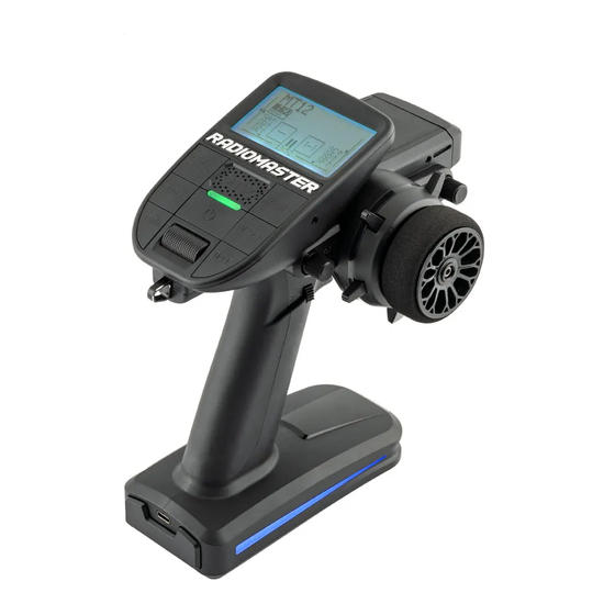
MT12
Instruction manual
Version:1.0
WWW.RADIOMASTERRC.COM
This manual is adapted from the EdgeTX online manual, which is provided and maintained by the EdgeTX team under
the
Creative Commons Attribution-ShareAlike 4.0 International (CC BY-SA 4.0)
license. Full credit is given to the EdgeTX
EdgeTX Online manual
team and contributors. More details can be found here:
Advertisement
Table of Contents

Subscribe to Our Youtube Channel
Related Manuals for RadioMaster MT12


Summary of Contents for RadioMaster MT12
- Page 1 MT12 Instruction manual Version:1.0 WWW.RADIOMASTERRC.COM This manual is adapted from the EdgeTX online manual, which is provided and maintained by the EdgeTX team under Creative Commons Attribution-ShareAlike 4.0 International (CC BY-SA 4.0) license. Full credit is given to the EdgeTX EdgeTX Online manual team and contributors.
-
Page 2: Table Of Contents
Contents 1. Overview ..................................4 1.1. Introduction ................................4 1.2. Safety information ..............................4 1.3. Radio overview ............................... 5 1.4. Battery and charging information .......................... 6 1.5. Manual and firmware download ..........................6 1.6. Specifications ................................. 6 1.7. Warranty and repair ............................... 7 1.8. - Page 3 7.1. Sensors ................................. 37 8.2. Sensor Configuration ............................38 8.3. Common Telemetry Sensors ..........................40 8. Display ..................................41 8.1. Display screen configuration ..........................41 9. Radio Settings ................................43 10.1. Tools ................................... 43 10.2. Radio Setup ................................ 43 10.3. Global Functions ..............................45 10.4.
-
Page 4: Overview
• In areas where local regulations prohibit the use of R/C models. WARNING! MT12 is pre-installed with the most stable firmware at the factory at time of release. please only attempt to update the firmware if you are confident in the process. Incorrect firmware updates may cause the remote control to... -
Page 5: Radio Overview
1.3. Radio overview... -
Page 6: Battery And Charging Information
1.4. Battery and charging information MT12 is powered by 2x 3.7V 18350 Lithium Ion cells and is charged using the built-in USB-C port. The charging circuitry is designed for charging 2x 3.7V Lithium Ion/Poly or 1x 7.4V Lipo battery pack only; the nominal voltage is 3.7V and the maximum charging voltage is 4.2V. -
Page 7: Warranty And Repair
If not handled properly, the RC model can cause serious injury or even death. If you decide to use EdgeTX firmware, you are solely responsible for your model. EdgeTX and RadioMaster are not liable for any injury or damage caused by using EdgeTX firmware or RadioMaster hardware. -
Page 8: Quick Start How-To Videos
1.9. How to BIND videos How to bind an R85C Receiver with a 4in1 MT12 How to bind an ER3C-I receiver with ExpressLRS MT12 2. User Interface 2.1. Button layout • [SYS] - System Button - Short press [SYS] button from the... -
Page 9: Main View
2.2. Main View Screen 1 - This view displays the model name, trim positions (if trims are enabled), clock, transmitter battery voltage, Drive mode, receiver signal strength, and Timers 1 and 2 (if enabled). Screen 2 - This view displays the model name, trim positions (if trims are enabled), clock, transmitter battery voltage, Drive mode, receiver signal strength, and Timer 1 (if enabled). -
Page 10: Reset
2.3 Reset Selecting Reset from the pop-up menu will give you the following options: Reset flight - When selected, this option: • Resets all timers configured with a persistence setting of Flight to zero. • Resets all discovered telemetry sensor values. •... - Page 11 The Debug screen provides data points used by the developers when debugging issues in the software. Most users will not find the information useful on this screen unless debugging issues with developers. The following debug information is provided. • Free mem - Current free radio memory in bytes. •...
-
Page 12: Custom Rgb Led Setup
The LUA scripts for RBG effects are in the “\SCRIPTS\RGBLED” folder of the MT12 SD card. To choose a colour or effect for your MT12 you can use one of the included LUA scripts, create your own LUA script or download a community made script and place it in the folder above. -
Page 13: Switch And Joystick Expansion Modules
2.6. Switch and Joystick Expansion Modules The MT12 features interchangeable expansion modules and includes a two 2 positions switch module and a 4 way Joystick module. You can choose the module you wish to install based on your own preferences. -
Page 14: Model Settings
3. Model Settings 3.1. Model Select Pressing the [MDL] button from the Main view will open the Model Select screen. Use the [Roller] or [Dial] to scroll through the model slots. Pressing [Enter] on an empty model slot will give you the following options: •... - Page 15 • To edit the text, using the [roller] or [dial], press the button, scroll to select the desired letter, then press the button again to move to the next space. To toggle between lower and upper case, long-press the button. Press the [RTN] button to exit out of text editing mode.
- Page 16 Minute (Minute Call) - If selected, you will be notified every minute that passes as described in the Count Down option. Count Down: • Silent - No notification is given until the timer reaches zero. When it reaches zero, you will hear one beep. •...
- Page 17 T-Source: The source that will be used for the throttle. T-Trim-Idle: When enabled, the throttle trim will only affect the bottom portion of the throttle band. For example, with Trim idle only enabled, the throttle stick at the lowest point might have a value of -80 and the center point will still be 0 and the highest point of 100.
- Page 18 Glob. Funs - When enabled, global functions programmed in the radio settings will apply to this model. When disabled, global functions will not apply to this model. ADC Filter - Enables/disables the ADC filter for this model. The global option will take the value designated in the radio settings, which is on by default.
- Page 19 However, this automatically assigned value can be manual changed. Note: In most cases, the default setting does not need to be changed. • Master / Bluetooth - Master mode using a Bluetooth connection (if installed in radio). • Slave / Bluetooth - Slave mode using a Bluetooth connection (if installed in radio). •...
- Page 20 • Ch 3 - Z Axis • Ch4 - X Rotation • Ch 5 - Y Rotation • Ch 6 - Z Rotation • Ch 7 - Dial • Ch 8 - Slider • CH 9 - Ch 32 - Buttons 1 - 24 In Advanced mode you can configure the following additional options: If mode (Interface mode): This indicates to the target device (the device you are connecting your transmitter to) what type of device you are connecting.
-
Page 21: Drive Modes
• Positions - The type of button that will be simulated. Push - will only map to one button 2POS - 8 POS - will map to the number of buttons that the switch has (ex: 3POS will map to 3 buttons). - Page 22 Drive modes Overview screen The Drive modes Overview screen shows an overview of the configured Drive modes. The information below is displayed for each Drive mode row: • Drive mode • Drive mode Name • Switch • Trim settings (RETA) Check FM Trims: When check FM trim is pressed, the trims for the current Drive mode are temporarily disabled.
- Page 23 Modifier - there are two possible value modifiers = and +. The = modifier uses the trim value directly from the selected Drive mode. The + modifier uses the trim value from the selected Drive mode and then adds the trim value from the Drive mode you are configuring.
-
Page 24: Setting Fail Safe
• Min - Defines the minimum that is allowed for the global variable. • Max - Defines the maximum value that is allowed for the global variable. • Popup - When enabled, a pop-up window will be displayed on the main screen when the value of this global variable changes during normal use. -
Page 25: Reversing A Servo
3.4. Reversing a Servo To change the direction of a servo movement, press the [MDL] button. Press [Page>] until you reach the “OUTPUTS” screen. Select the channel that you wish to reverse the servo out put on with the roller. Press enter and select “Edit”. Use the roller to scroll to “Direction”... -
Page 26: Setting End Points
3.7. End points To change the end points of a channel, press the [MDL] button. Press [Page>] until you reach the “OUTPUTS” screen. Select the channel that you wish to change the end point on with the roller. Press enter and select “Edit”. Use the roller to scroll to select “Min”... -
Page 27: Inputs, Mixes & Outputs
Inputs, Mixes & Outputs To be able to support many different types of radio transmitters, EdgeTX uses a generic control data flow that can be applied to any radio transmitter. In this data flow, any of the radio's physical controls (sticks, switches, sliders, pots) can be mapped to an input in the software. -
Page 28: Input Configuration Page
Inputs screen The inputs screen shows you an overview of your configured inputs. Each row represents an input line and displays the following information from left to right: Input name, weight, activation switch, line name. These items are described in the Input configuration page area below. - Page 29 Offset - The value added to or subtracted from the input source. Curve - Specifies the type of curve that will be used. The following curve options exist: • Diff - Multiplies only the range above or below the middle (0) by the specified %. •...
-
Page 30: Mixes
3.7. Mixes The Mixes screen is where several Inputs can be combined into one "Channel Mix". These mixes are then assigned to a radio channel for output. This is also the place where switches, knobs or sliders are assigned to a channel for output. -
Page 31: Outputs
• Weight- Percentage of the source value to use. Long-pressing here will switch from numerical value to a global variable. • Offset - The value added to or subtracted from the source. • Trim - Specifies whether or not to include the trim values in this mix. For the trim values to be included, the trim field for the relevant input must also be enabled on INPUTS screen. -
Page 32: Curves
Outputs Configuration page The output configuration screen has the following configuration options: • Name - Name for the Output up to 6 characters. • Subtrim - The subtrim value (max 100). It can also be set to a global variable by pressing the ldong-pressing the [Enter] button to switch to GV Mode and then selecting the desire global variable. -
Page 33: Logical Switches
The curve configuration screen has the following configurable options: • Name - Name for the curve. Only 3 characters are possible. • Type - Type of curve: Options are Standard and Custom Standard - Horizontal axis points are fixed values based on the number of points. Vertical axis points are adjustable. -
Page 34: Special Functions
Logical Switches Configuration Screen After selecting to edit a logical switch, you will have the following configuration options: • Func - The logical function that you want to use. See Logical Switch Functions below for a description of the possible functions you can use. •... - Page 35 Functions Below are all the available functions in EdgeTX, what they do, as well as what additional configuration options that will be shown when the function is selected. Override (Channel Override) - Overrides the defined channel with the defined value. •...
- Page 36 • Repeat - Frequency to repeat the vibration pattern. Options are !1x (do not vibrate at startup even if the switch is active), 1x (vibrate once), 1s thru 60s (vibrate every xx seconds). SD Logs - Creates a log .csv file of the radio and telemetry values in the LOGS folder on the SD Card. The radio will create a new entry into the log file based on the frequency configured in the Value setting.
-
Page 37: Telemetry
7. Telemetry Telemetry is data received from the model to the radio from various sensors. These sensors may be included in the radio receiver or flight controller or may be separate sensors, such as GPS, variometer, or magnetometer. The received telemetry data can be displayed by EdgeTX in widgets, configured in alarms or audio call-outs. -
Page 38: Sensor Configuration
RX Status Rqly Portion of Telemetry screen Here you can configure the threshold for the RX alarms. The Rx-Stats label will change (Rx-Stats, RSSI, Rqly, Sgnl) depending on the protocol that is used with the model. • Low alarm - The threshold value when the "RF signal low" voice prompt will be played. The recommended value is 45. - Page 39 • Type: Options are custom or calculated. Custom sensors are defined by the hardware. Calculated sensors are a sensors whose value is calculated using other sensors values. See below for more information on calculated sensors. • ID: This number indicates what type of sensor it is. It contains two parts. The first part is the ID number which defines the sensor type.
-
Page 40: Common Telemetry Sensors
8.3. Common Telemetry Sensors Each sensor has two auto generated sensors for their minimum and maximum values. They share the same name with a negative and positive symbol added to the end. For example: RXBt + This dispalys the maximum value that the sensor attained during the flight. -
Page 41: Display
8. Display 8.1. Display screen configuration The Display screen is where you configure the telemetry screens shown when pressing the [Tele] button from the main screen. You can configure up to Four telemetry screens. You can choose one of the following display types for each screen: Nums (Numbers) - The numbers type displays the number value of the selected telemetry sensor or other configured object. - Page 42 Display Script Configuration Display Screen with fm2m Lua Script Additional Lua scripts for EdgeTX can be found here: https://github.com/EdgeTX/lua-scripts To configure the screens, scroll to the screen you want to configure and then press the [Enter] button. Then scroll to select the type of screen that you want to use and press the [Enter] button to select it. Depending on the selected screen type, you can then configure the telemetry objects for each cell by scrolling to the desired object and selecting it by pressing the [Enter] button.
-
Page 43: Radio Settings
9. Radio Settings 10.1. Tools Pressing the [SYS] button from the Main view will open the Tools screen. The Tools page in Radio Settings is where you can select Lua script-based tools for execution. Lua scripts that are located on the SD card in the Tools folder will be listed here. Selecting a tool will execute it. By default, EdgeTX includes several tools. - Page 44 Wav volume - The volume for alerts and warnings and sounds that are played with the Play track special function Bg volume - The volume for background .wav files (music) that are played with the BGMusic special function Vario (Variometer) Volume - Volume for variometer beeps Pitch zero - Low pitch frequency Pitch max - High pitch frequency...
-
Page 45: Global Functions
Units - Units of measure. Options are metric or imperial. Play delay (sw. mid pos) - The minimum time in milliseconds a switch must be in the middle position before a special function will get activated. This is used to prevent the middle position from being activated on a three-position switch when switching from low position to high position. -
Page 46: Hardware
10.5. Hardware The Hardware screen is where you configure hardware specific-settings for your radio. It shows all physical hardware objects (sticks, pots, switches) and allows for their modifications. It is also where you can calibrate your sticks and pots. It also contains additional configuration options. Hardware Screen Calibration To calibrate your physical radio controls (sticks, pots, sliders, &... - Page 47 Internal RF Type - Select the module type for the internal module bay. Options are: Multi, XJT, ISRM, CRSF. When CRSF is selected, you can also select the baud rate. You can read more about baud rates here. Sample Mode (External RF)- Options are Normal and OneBit. The default setting of Normal should be used by most users.
-
Page 48: Version
10.6. Version Version The Version screen displays information about the current EdgeTX version that is being used: Version Screen • FW - Firmware name • VERS - Firmware version • NAME: Firmware Codename • DATE - Date & time the firmware was compiled Firmware Options To view the build options that were enabled when compiled, highlight the [Firmware options] options and press the [Enter] button. -
Page 49: Special Thanks
11.1 Special thanks Special thanks to all the people and groups that contributed (directly or indirectly) to online EdgeTX user manual this document is based on. Many great tutorials and how-to guides can be found from these contributors on their youtube channels and web sites.
Need help?
Do you have a question about the MT12 and is the answer not in the manual?
Questions and answers