
Subscribe to Our Youtube Channel
Related Manuals for attocube ECC100


Summary of Contents for attocube ECC100
- Page 1 Version: Modified: October 2018 Products: ECC100, DAISY Software ECC100 ECS-Positioner Controller User Manual...
-
Page 2: Table Of Contents
IV.1.1. ECC Settings ............18 IV.1.2. ECC Ethernet settings ..........22 IV.1.3. Controlling Positioners with the GUI ......23 IV.2. Connect to a specific ECC100 with the DAISY ...... 27 IV.2.1. Startup ..............27 IV.2.2. Configuring ECC ID settings ......... 27 IV.3. -
Page 3: Safety Information
Functional (EMC) earth/ground terminal. Page 1 © 2001-2018 attocube systems AG. Product and company names listed are trademarks or trade names of their respective companies. Any rights not expressly granted herein are reserved. ATTENTION: Specifications and technical data are subject to change without notice. -
Page 4: Table Of Contents
If malfunction of the controller is suspected, please immediately contact attocube systems for repair or replacement. Take special care if you connect products of other manufacturers to the controller. Follow the General Accident Prevention Rules. -
Page 5: Declarations Of Conformity
Page 3 © 2001-2018 attocube systems AG. Product and company names listed are trademarks or trade names of their respective companies. Any rights not expressly granted herein are reserved. ATTENTION: Specifications and technical data are... -
Page 6: Waste Electrical And Electronic Equipment (Weee) Directive
Waste treatment on your own responsibility If you do not return an “end of life” unit to attocube systems, you must hand it to a company specialized in waste recovery. Do not dispose of the unit in a litter bin or at a public waste disposal site. -
Page 7: System Overview
Page 5 © 2001-2018 attocube systems AG. Product and company names listed are trademarks or trade names of their respective companies. Any rights not expressly granted herein are reserved. ATTENTION: Specifications and technical data are... - Page 8 Page 6...
-
Page 9: Setup Procedure
(NUM or NUM+)! Page 7 © 2001-2018 attocube systems AG. Product and company names listed are trademarks or trade names of their respective companies. Any rights not expressly granted herein are reserved. ATTENTION: Specifications and technical data are... -
Page 10: Ii.2. Electrical Installation
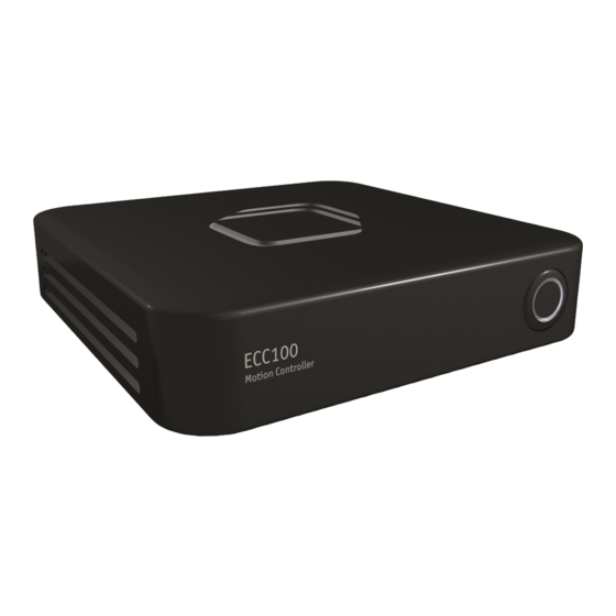
II.2. Electrical Installation To start the ECC100 Motion Controller, please connect the controller to the voltage supply and press the round power button on the front panel. Warning. The unit must be connected to a grounded and fused line voltage supply with a voltage ranging from 95 V to 250 V and a line frequency ranging from 50 Hz to 60 Hz. -
Page 11: Ii.2.2. Positioner Control Cables
Page 9 © 2001-2018 attocube systems AG. Product and company names listed are trademarks or trade names of their respective companies. Any rights not expressly granted herein are reserved. ATTENTION: Specifications and technical data are... -
Page 12: Ii.2.3. How To Connect A Positioner
Cable optional Optional vacuum feedthrough: In addition to all attocube positioning systems, specific vacuum feedthroughs are optionally available. As an example, the image below depicts a feedthrough for a single /NUM-positioner. Vacuum feedthroughs for multiple axes are also available. For more information please visit us at http://attocube.com/nanoPOSITIONING/feedthroughs.htm... -
Page 13: Ii.2.4. Pin Assignment Of The Axis Outputs
Specific vacuum feedthroughs are available as an option for all attocube positioning systems. Page 11 © 2001-2018 attocube systems AG. Product and company names listed are trademarks or trade names of their respective companies. Any rights not expressly granted herein are reserved. ATTENTION: Specifications and technical data are... -
Page 14: Ii.2.5. Pin Assignment Of The Gpio-Port
The pin assignment of the female 26-pin Sub-D connector at the rear side of the ECC100 for the trigger output and input signals is given in the table below:... - Page 15 Page 13 © 2001-2018 attocube systems AG. Product and company names listed are trademarks or trade names of their respective companies. Any rights not expressly granted herein are reserved. ATTENTION: Specifications and technical data are...
-
Page 16: Software
32-bit and 64-bit versions. Corresponding drivers are included on the installation CD. Note. In order to control the ECC100 Motion Controller via a computer, both hardware driver and DAISY software need to be installed. Driver and software are installed separately, see sections III.3 and III.4. - Page 17 Accept the installation on the next window. Page 15 © 2001-2018 attocube systems AG. Product and company names listed are trademarks or trade names of their respective companies. Any rights not expressly granted herein are reserved. ATTENTION: Specifications and technical data are...
-
Page 18: Iii.4. Daisy Software Installation
The next and last window shows if the installation was successful. III.4. DAISY Software Installation For the installation of the DAISY software, please copy the folder \Software\ ECC100_Software\ECC100_GUI on the enclosed CD and all of its contents to a new folder on your hard drive. In order to launch the software, simply execute the file daisy.exe within the new folder (an installation of the software is not required). -
Page 19: Graphical User Interface (Gui)
GUI and guarantees an accurate positioning. Page 17 © 2001-2018 attocube systems AG. Product and company names listed are trademarks or trade names of their respective companies. Any rights not expressly granted herein are reserved. ATTENTION: Specifications and technical data are... -
Page 20: Iv.1.1. Ecc Settings
When Daisy is started a popup will appear, if the version of the flashed firmware and the firmware found on the pc don’t match. This popup is only an information and not an error. The “PRO-Popup” will inform the user if the PRO-features of the used ECC100 are enabled. IV.1.1. ECC Settings In the “ECC Settings”-tab the Actor Name must be identified in the first input... - Page 21 12. Page 19 © 2001-2018 attocube systems AG. Product and company names listed are trademarks or trade names of their respective companies. Any rights not expressly granted herein are reserved. ATTENTION: Specifications and technical data are...
- Page 22 Quadrature In available only with PRO version The ‘Quadrature In’ trigger updates the target position for closed loop positioning. To actually control the positioner, the “move” button must be activated [see IV.1.3] Enable: When the Enable box is checked, the input trigger will change to a quadrature trigger with the resolution entered in the ‘Resolution’...
- Page 23 ‘Clock’ values. Page 21 © 2001-2018 attocube systems AG. Product and company names listed are trademarks or trade names of their respective companies. Any rights not expressly granted herein are reserved. ATTENTION: Specifications and technical data are subject to change without notice.
-
Page 24: Iv.1.2. Ecc Ethernet Settings
Enter in the command line: route ADD 224.0.0.0 MASK 240.0.0.0 IF 10.10.1.61 The last IP (here: 10.10.1.61) stands for the port where the ECC100 is connected to. The range 224.0.0.0 up to 239.255.255.255 is reserved only for multicasts. Page 22... -
Page 25: Iv.1.3. Controlling Positioners With The Gui
“deg”. Page 23 © 2001-2018 attocube systems AG. Product and company names listed are trademarks or trade names of their respective companies. Any rights not expressly granted herein are reserved. ATTENTION: Specifications and technical data are subject to change without notice. - Page 26 However, the automatic positioning can be stopped at any time by - pressing the “Move” button again or any manual positioning button. Manual Positioning By operating the control within the “Manual Positioning” window, a positioner connected to the ECC100 can be driven manually via the software interface. Page 24...
- Page 27 Page 25 © 2001-2018 attocube systems AG. Product and company names listed are trademarks or trade names of their respective companies. Any rights not expressly granted herein are reserved. ATTENTION: Specifications and technical data are subject to change without notice.
- Page 28 Reference options available only with the PRO version Update Ref will update the reference position every time reference marker is hit. When this function is disabled, the reference marker will be considered only the first time and therefore ignored. Auto Reset resets the position each time the reference marker is detected. Target Range available only with the PRO version...
-
Page 29: Iv.2. Connect To A Specific Ecc100 With The Daisy
Page 27 © 2001-2018 attocube systems AG. Product and company names listed are trademarks or trade names of their respective companies. Any rights not expressly granted herein are reserved. ATTENTION: Specifications and technical data are... -
Page 30: Iv.4. Upgrading
ECC100 with all addition features enabled To obtain more functions on the ECC such as “End Of Travel “ detection, multi device, static voltage or advanced trigger options the ECC100-software can be upgraded. The features “PRO” and “SYNC” can be unlocked by a feature code provided by attocube. -
Page 31: Iv.5. Installing New Positioner Profiles
DAISY window. Page 29 © 2001-2018 attocube systems AG. Product and company names listed are trademarks or trade names of their respective companies. Any rights not expressly granted herein are reserved. ATTENTION: Specifications and technical data are... -
Page 32: Firmware Update
The firmware must be stored in: ..\Software\ECC100\ECC100_GUI\firmware Choose the specific ECC and press the “Flash”-button. Firmware on the ECC100 and in the folder are the same Firmware on the ECC100 is newer than in the folder. versions. It’s not necessary to flash the firmware. -
Page 33: Vi. Dll
Page 31 © 2001-2018 attocube systems AG. Product and company names listed are trademarks or trade names of their respective companies. Any rights not expressly granted herein are reserved. ATTENTION: Specifications and technical data are subject to change without notice. - Page 34 ECC_ControlContinousBkwd Controls continous movement in backward direction “false” stops any movement ECC_ControlContinousFwd Controls continous movement in forward direction “false” stops any movement ECC_ControlDevice Sets and retrieve the device identifier ECC_ControlEotOutputDeactivate Deactivates output on end-of-travel ECC_ControlExtTrigger Controls the input trigger for steps ECC_ControlFixOutputVoltage Controls the DC level on the output ECC_ControlFrequency...
- Page 35 Triggers a single step in desired direction Page 33 © 2001-2018 attocube systems AG. Product and company names listed are trademarks or trade names of their respective companies. Any rights not expressly granted herein are reserved. ATTENTION: Specifications and technical data are...
- Page 36 Main office attocube systems AG Eglfinger Weg 2 D-85540 Haar D-80539 München Germany www.attocube.com Phone +49 89 2877 80915 +49 89 2877 80919 E-Mail info@attocube.com North America Support Hotlines: (East Coast Office) Phone +1 212 962 6930 (West Coast Office)
- Page 37 Page 35 © 2001-2018 attocube systems AG. Product and company names listed are trademarks or trade names of their respective companies. Any rights not expressly granted herein are reserved. ATTENTION: Specifications and technical data are subject to change without notice.
Need help?
Do you have a question about the ECC100 and is the answer not in the manual?
Questions and answers