
Related Manuals for attocube ANC300


Summary of Contents for attocube ANC300
- Page 1 Version: Modified: January 2014 Products: ANC300, ANM150, ANM200, ANM300 Firmware: 18-04-2012 User Manual Piezo Positioning Electronic ANC300...
- Page 2 You may obtain a complete corresponding machine-readable copy of the source code of such software under the GPL or LGPL from attocube systems. attocube sys- tems offers to provide such source code to you on CD-ROM for a charge covering...
-
Page 3: Table Of Contents
USB Slave Port ............43 Page 3 © 2001-2014 attocube systems AG. Product and company names listed are trademarks or trade names of their respective companies. Any rights not expressly granted herein are reserved. ATTENTION: Specifications and technical data are subject... - Page 4 IV.1.c. USB Master Port............44 IV.1.d. RS232 Port .............. 44 IV.2. Remote Control ..............44 IV.2.a. Standard Console Commands........45 IV.2.b. Example Console Session..........47 IV.2.c. Programming new patterns ......... 48 IV.2.d. Lua Console............. 49 IV.3. LabView™ Drivers.............. 53 Upgrades and Add-ons ............58 V.1.
-
Page 5: List Of Abbreviations
Line Feed. ASCII character code 10. Page 5 © 2001-2014 attocube systems AG. Product and company names listed are trademarks or trade names of their respective companies. Any rights not expressly granted herein are reserved. ATTENTION: Specifications and technical data are subject... - Page 6 Industry standard that defines characteristics of a serial, binary, single- ended port. Used as synonym for COM port. Seconds. The unit of time. Step. Used in conjunction with the stepping functionality of the ANC300. Sub-D Subminiature D-type connector. Industry standard for serial connectors, which is subdivided by the number of electrical pins on the connector, e.g.
-
Page 7: Introduction
Page 7 © 2001-2014 attocube systems AG. Product and company names listed are trademarks or trade names of their respective companies. Any rights not expressly granted herein are reserved. ATTENTION: Specifications and technical data are subject... -
Page 8: Safety Information
Warnings, Cautions, and Notes throughout this user manual and, where visible, on the ANC300 itself. I.2.a. Safety Symbols on the Equipment WARNING. Risk of electric shock. High voltages present. -
Page 9: I.2.B. Safety Symbols In This Manual
. Clarification of an instruction or additional information. Page 9 © 2001-2014 attocube systems AG. Product and company names listed are trademarks or trade names of their respective companies. Any rights not expressly granted herein are reserved. ATTENTION: Specifications and technical data are subject... -
Page 10: I.2.C. Warnings
WARNING. Risk of electric shock. If covers are opened, there is a risk to touch hazardous voltages. If malfunction is suspected, immediately con- tact attocube systems for repair or replacement. Modified or opened elec- tronics cannot be covered by the attocube warranty anymore. Only per- sonnel trained in the servicing and maintenance of this equipment should remove its covers or attempt any repairs or adjustments. -
Page 11: Declarations Of Conformity
EMC EN61326: 1997 Page 11 © 2001-2014 attocube systems AG. Product and company names listed are trademarks or trade names of their respective companies. Any rights not expressly granted herein are reserved. ATTENTION: Specifications and technical data are subject to change without notice. -
Page 12: Waste Electrical And Electronic Equipment (Weee) Directive
Waste treatment on your own responsibility If you do not return an "end of life" product to attocube systems, you must hand it to a company specialized in waste recovery. Do not dispose of the unit in a litter bin or at a public waste disposal site. -
Page 13: Ii.setup Procedure
Page 13 © 2001-2014 attocube systems AG. Product and company names listed are trademarks or trade names of their respective companies. Any rights not expressly granted herein are reserved. ATTENTION: Specifications and technical data are subject to change without notice. -
Page 14: Ii.2.B. Fuses
2) After switching off, always wait 2 minutes before opening the ANC300, and before removing or inserting any module or card. 3) Always replace broken fuses with fuses of the same type and rating. Two main fuses are located on the back panel for the mains voltage. - Page 15 Connect to mains voltage and switch on to check the functionality. Page 15 © 2001-2014 attocube systems AG. Product and company names listed are trademarks or trade names of their respective companies. Any rights not expressly granted herein are reserved. ATTENTION: Specifications and technical data are subject...
-
Page 16: Ii.3. Front Panel Controls And Indicators
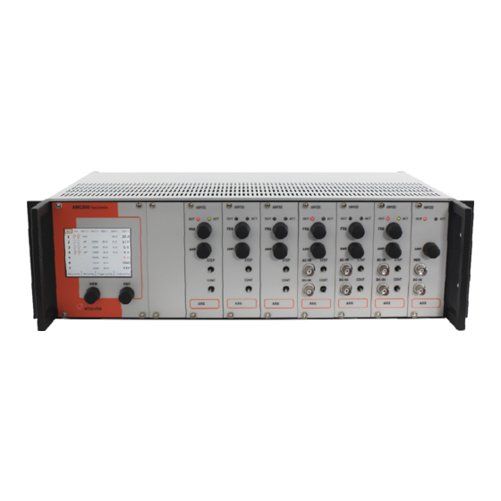
II.3. Front Panel Controls and Indicators Figure 1: Front panel of the ANC300 with seven ANM modules in place. The front panel is arranged as follows: 1) Main display with touch screen functionality (CPU behind it), 2) View knob to move the focus in the main screen, 3) Edit knob to change values and activate options, 4) Power supply. - Page 17 Page 17 © 2001-2014 attocube systems AG. Product and company names listed are trademarks or trade names of their respective companies. Any rights not expressly granted herein are reserved. ATTENTION: Specifications and technical data are subject...
-
Page 18: Ii.4. Back Panel Connections
II.4. Back Panel Connections Figure 3: Back panel of the ANC 300 piezo positioning electronic On the back panel, there are: 1) voltage selector (100 / 115 / 230 V) with integrated fuse holder (see fuse description above), 2) main power switch, 3) main power supply connector, (IEC connector, 100 / 115 / 230 V, each +/- 10%, 50 / 60 Hz, max. - Page 19 BNC. Page 19 © 2001-2014 attocube systems AG. Product and company names listed are trademarks or trade names of their respective companies. Any rights not expressly granted herein are reserved. ATTENTION: Specifications and technical data are subject...
-
Page 20: Ii.5. Pin Assignment
II.5. Pin Assignment II.5.a. Trigger Port The pin assignment of the 25 pin Sub-D connector (trigger port) as seen on the back panel of the electronics is given in the table below: Trigger Default Trigger Default Name Name Axis 1 UP Axis 1 DOWN Axis 2 UP Axis 2 DOWN... -
Page 21: Description Of The Controller And General Use
Page 21 © 2001-2014 attocube systems AG. Product and company names listed are trademarks or trade names of their respective companies. Any rights not expressly granted herein are reserved. ATTENTION: Specifications and technical data are subject to change without notice. -
Page 22: Iii.2. Main Graphical User Interface
Main Graphical User Interface III.2.a. Start-up Screens When starting the ANC300, the screen at first shows the logo screen fol- lowed by the initialization procedure. Then, the internal bus is scanned for present modules and their types. The type and the serial numbers are listed at their respective position. The sys- tem is then configured accordingly. -
Page 23: Iii.2.B. General Usage Of The Anc300 Gui
Press EXIT to go back to the Main Screen. Page 23 © 2001-2014 attocube systems AG. Product and company names listed are trademarks or trade names of their respective companies. Any rights not expressly granted herein are reserved. ATTENTION: Specifications and technical data are subject... -
Page 24: Iii.2.D. Feature Codes
(IP address): DHCP or Manual setting. If set to DHCP, the ANC300 tries to find a DHCP master in the LAN and will query for a valid address. -
Page 25: Iii.2.F. Trigger Configuration Dialog
Page 25 © 2001-2014 attocube systems AG. Product and company names listed are trademarks or trade names of their respective companies. Any rights not expressly granted herein are reserved. ATTENTION: Specifications and technical data are subject... -
Page 26: Iii.2.G. Limits Configuration Dialog
III.2.g. Limits Configuration Dialog In the limit configuration dialog, the user can activate certain limit set- tings per axis. Choose one of two limit sets, Room Temperature or Low Temperature. This setting allows choosing different limit settings for e.g. two different temperatures. Note . -
Page 27: Iii.3. Anm300 Module
The AC-IN is added after the amplifier. Page 27 © 2001-2014 attocube systems AG. Product and company names listed are trademarks or trade names of their respective companies. Any rights not expressly granted herein are reserved. ATTENTION: Specifications and technical data are subject... -
Page 28: Iii.3.A. Anm300 Front Panel Usage
III.3.a. ANM300 Front Panel Usage By turning or pressing any knob on a certain module front plate, the axis screen as shown in Figure 5 below will appear. Another way to get to the axis screen is to select the axis from the main overview list, or to cycle to the axis by clicking on the axis button repeatedly. -
Page 29: Iii.3.B. Anm300 Axis Screen Elements And Usage
17) Ground switch. Press to set the axis module to ground. Page 29 © 2001-2014 attocube systems AG. Product and company names listed are trademarks or trade names of their respective companies. Any rights not expressly granted herein are reserved. ATTENTION: Specifications and technical data are subject... -
Page 30: Iii.3.C. Stepping Functionality
III.3.c. Stepping Functionality The stepping output signal is by default a sawtooth wave. See section IV.2.c on programming new patterns. One step corresponds either to a linear rise to the nominal voltage in time t = 1/frequency and a steep decrease to zero (on the order of 10 – 20 µs), or a steep increase to the step voltage and a linear decrease. -
Page 31: Iii.3.D. Offset Voltage Functionality
Page 31 © 2001-2014 attocube systems AG. Product and company names listed are trademarks or trade names of their respective companies. Any rights not expressly granted herein are reserved. ATTENTION: Specifications and technical data are subject... -
Page 32: Iii.3.E. Dc-In Functionality
III.3.e. DC-IN Functionality There are two BNCs on the module frontplate, labeled DC-IN and AC-IN. The DC-IN input accepts -10 .. +10 V, while the output is (nominally) 0 .. +150 V. The gain is 15 (see Figure 6). Note. It is possible to input negative voltages on the DC-in of up to -10 V in order to pull down a positive offset voltage. -
Page 33: Iii.3.F. Ac-In Functionality
Page 33 © 2001-2014 attocube systems AG. Product and company names listed are trademarks or trade names of their respective companies. Any rights not expressly granted herein are reserved. ATTENTION: Specifications and technical data are subject to change without notice. -
Page 34: Iii.3.H. Gnd Functionality
III.3.h. GND Functionality Upon pressing of the GND button, the ANM300 will disable all AC-IN, DC- IN, Stepping, and Offset functionality and will connect the outputs to chassis mass. Note. Connecting the piezoelectric actuator leads to a mass is important in order to reduce electro-mechanical noise on the actuator that might be produced by the electronics. -
Page 35: Iii.3.I. Capacitance Measurement
Page 35 © 2001-2014 attocube systems AG. Product and company names listed are trademarks or trade names of their respective companies. Any rights not expressly granted herein are reserved. ATTENTION: Specifications and technical data are subject... -
Page 36: Iii.3.J. Limit Functionality
Hence, it is mandatory to measure the capacitance before applying any voltage to the outputs, in order to protect the ANC300 and the position- ers. Page 36... - Page 37 1000 Page 37 © 2001-2014 attocube systems AG. Product and company names listed are trademarks or trade names of their respective companies. Any rights not expressly granted herein are reserved. ATTENTION: Specifications and technical data are subject to change without notice.
-
Page 38: Iii.4. Anm150 Module
III.4. ANM150 Module The ANM150 module is an open loop positioning module. The nominal output voltage is unipolar from 0 .. +150 V. The outputs are protected against short-circuits and have a current limiter in order to protect them. The following functions are available (see schematic graph below): Stepping with up to 150 V or up to 10 kHz rate (see section III.3.j on •... -
Page 39: Iii.4.A. Anm150 Axis Screen Elements And Usage
17) Ground switch. Press to set the axis module to ground. Page 39 © 2001-2014 attocube systems AG. Product and company names listed are trademarks or trade names of their respective companies. Any rights not expressly granted herein are reserved. ATTENTION: Specifications and technical data are subject... -
Page 40: Iii.5. Anm200 Module
III.5. ANM200 Module The ANM200 module is an open loop, low noise scanning module. The nominal output voltage is unipolar from 0 .. +150 V. The outputs are pro- tected against short-circuits and have a current limiter in order to protect them. -
Page 41: Iii.5.A. Anm200 Axis Screen Elements And Usage
17) Ground switch. Press to set the axis module to ground. Page 41 © 2001-2014 attocube systems AG. Product and company names listed are trademarks or trade names of their respective companies. Any rights not expressly granted herein are reserved. ATTENTION: Specifications and technical data are subject... - Page 42 Figure 12: Frequency response of the ANM300 DC-IN input. Figure 13: Frequency response of the ANM200 MOD modulation input. Note that the gain is 0.01 up to a frequency of 10 kHz. Page 42...
-
Page 43: Remote Control Of The Anc300
Page 43 © 2001-2014 attocube systems AG. Product and company names listed are trademarks or trade names of their respective companies. Any rights not expressly granted herein are reserved. ATTENTION: Specifications and technical data are subject... -
Page 44: Iv.1.C. Usb Master Port
IV.1.d. RS232 Port The RS232 port on the backside of the ANC300 can be used to connect to a PC in order to establish a serial connection. The correct settings for the port are 38400 baud, 8 data bits, no parity, 1 stop bit, no flow control. -
Page 45: Iv.2.A. Standard Console Commands
• Page 45 © 2001-2014 attocube systems AG. Product and company names listed are trademarks or trade names of their respective companies. Any rights not expressly granted herein are reserved. ATTENTION: Specifications and technical data are subject to change without notice. - Page 46 not modified, while an offset function would be turned off. off: This enables offset mode. AC-IN and DC-IN functionalities are • not modified, while any stepping would be turned off. stp+: This enables additive offset + stepping mode. Stepping wave- •...
-
Page 47: Iv.2.B. Example Console Session
= 0.000000 V Page 47 © 2001-2014 attocube systems AG. Product and company names listed are trademarks or trade names of their respective companies. Any rights not expressly granted herein are reserved. ATTENTION: Specifications and technical data are subject... -
Page 48: Iv.2.C. Programming New Patterns
The time for each individual step is t= 1/256 * 1/f, with f being the chosen frequency. In the ANC300, the up and down patterns stored on each respective mod- ule can be modified individually. Figure 14: Default Up and Down Patterns. -
Page 49: Iv.2.D. Lua Console
Page 49 © 2001-2014 attocube systems AG. Product and company names listed are trademarks or trade names of their respective companies. Any rights not expressly granted herein are reserved. ATTENTION: Specifications and technical data are subject... - Page 50 In the same way, the output trigger values can be modified: > trig1.value = 1 This will set to output trigger no. 1 to high level (3.3 V). Set it to 0 again to commence the trigger pulse. The trigger object only has the .value property.
- Page 51 > test(5) Page 51 © 2001-2014 attocube systems AG. Product and company names listed are trademarks or trade names of their respective companies. Any rights not expressly granted herein are reserved. ATTENTION: Specifications and technical data are subject to change without notice.
- Page 52 This example shows that in Lua it is possible to program functions and subroutines, which enables much more sophisticated possibilities than only calling single commands. The great advantage versus having a pro- gram running on a PC is that delays due to repetitive commands through the serial communication are minimized.
-
Page 53: Iv.3. Labview™ Drivers
This VI closes the communication channel. Page 53 © 2001-2014 attocube systems AG. Product and company names listed are trademarks or trade names of their respective companies. Any rights not expressly granted herein are reserved. ATTENTION: Specifications and technical data are subject... - Page 54 This VI controls the AC-IN and DC-IN inputs. set /get determines whether the value is written or read. Use ON/OFF re- spectively. Transfer ok is true when the command was successful. Data out is the direct response from the ANC300. Page 54...
- Page 55 ANC300. Page 55 © 2001-2014 attocube systems AG. Product and company names listed are trademarks or trade names of their respective companies. Any rights not expressly granted herein are reserved. ATTENTION: Specifications and technical data are subject...
- Page 56 The serial number is given in Serial. The program determines whether a valid serial number was returned and writes this result to Serial OK. Data out is the direct response from the ANC300. ANC300_trigger_setget.vi ANC300_trigger_SetGet.vi reads and writes trigger status.
- Page 57 Page 57 © 2001-2014 attocube systems AG. Product and company names listed are trademarks or trade names of their respective companies. Any rights not expressly granted herein are reserved. ATTENTION: Specifications and technical data are subject...
-
Page 58: Upgrades And Add-Ons
4. Login as user “update” with password “123456” (default). 5. Select binary protocol and upload the update file. 6. In case a mating update file is sent, the ANC300 will load and in- stall the update. During the update procedure, the ANC300 might restart once or twice. -
Page 59: Removal Of An Axis Module
. The ANC300 may not be used with the front cover open. Page 59 © 2001-2014 attocube systems AG. Product and company names listed are trademarks or trade names of their respective companies. Any rights not expressly granted herein are reserved. ATTENTION: Specifications and technical data are subject... -
Page 60: Installation Of An Axis Module
After mains and all other cabling have been removed, open the cover of a free slot in the ANC300. Carefully insert the module taking care not to touch the electronics with bare hands to avoid damages due to static elec- tricity. -
Page 61: Preventive Maintenance
Page 61 © 2001-2014 attocube systems AG. Product and company names listed are trademarks or trade names of their respective companies. Any rights not expressly granted herein are reserved. ATTENTION: Specifications and technical data are subject... -
Page 62: Questions & Answers
ANC300 in case the clicking cannot be stopped. Q) One axis of the ANC300 has no output and the red LED on one or more modules is blinking. A) The ANM modules feature overheat protection and shut down when too much heat is generated. - Page 63 Also, we suggest applying a combination of different techniques. Page 63 © 2001-2014 attocube systems AG. Product and company names listed are trademarks or trade names of their respective companies. Any rights not expressly granted herein are reserved. ATTENTION: Specifications and technical data are subject...
- Page 64 Main office attocube systems AG Königinstrasse 11a (Rgb) D-80539 München Germany www.attocube.com Phone +49 89 2877 80915 +49 89 2877 80919 E-Mail info@attocube.com North America Support Hotlines: (East Coast Office) Phone +1 212 962 6930 (West Coast Office) Phone +1 510 649 9245...
Need help?
Do you have a question about the ANC300 and is the answer not in the manual?
Questions and answers