
Related Manuals for GORMAN-RUPP PUMPS 03H1-GR /S3


Summary of Contents for GORMAN-RUPP PUMPS 03H1-GR /S3
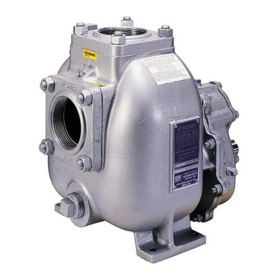
- Page 1 OM‐07248-02 June 23, 2020 Rev B 8/26/21 INSTALLATION, OPERATION, AND MAINTENANCE MANUAL WITH PARTS LIST 0 SERIES PUMP MODEL 03H1-GR /S3 GORMAN‐RUPP PUMPS www.grpumps.com e2020 Gorman‐Rupp Pumps Printed in U.S.A.
- Page 2 Register your new Gorman‐Rupp pump online at www.grpumps.com Valid serial number and e‐mail address required. RECORD YOUR PUMP MODEL AND SERIAL NUMBER Please record your pump model and serial number in the spaces provided below. Your Gorman‐Rupp distributor needs this information when you require parts or service. Pump Model: Serial Number:...
-
Page 3: Table Of Contents
TABLE OF CONTENTS INTRODUCTION ..........PAGE I - 1 SAFETY SECTION A... - Page 4 TABLE OF CONTENTS (continued) PARTS LISTS: Pump Model ............PAGE E - 3 Gear Box Assembly .
-
Page 5: Introduction
0 SERIES OM-07248 INTRODUCTION Thank You for purchasing a Gorman‐Rupp pump. HAZARD AND INSTRUCTION Read this manual carefully to learn how to safely DEFINITIONS install and operate your pump. Failure to do so could result in personal injury or damage to the The following are used to alert maintenance per... -
Page 6: Safety Section A
0 SERIES OM‐07248 SAFETY - SECTION A This information applies to 0 Series power take‐off pumps. Refer to the man ual accompanying the power source be fore attempting to begin operation. Be certain proper safety practices are followed before operating or servicing Because pump installations are seldom the pump. - Page 7 OM-07248 0 SERIES to disconnect the drive shaft or remove the pump. Be sure the pump is properly reinstalled and secure before opera tion. Do not operate the pump against a closed discharge valve for long periods of time. If operated against a closed dis charge valve, pump components will deteriorate, and the liquid could come Do not remove plates, covers, gauges,...
-
Page 8: Installation - Section B
0 SERIES OM-07248 INSTALLATION - SECTION B Review all SAFETY information in Section A. coming pressure to 50% of the maximum permissi ble operating pressure as shown on the pump per Since pump installations are seldom identical, this formance curve (see Section E, Page 1). section offers only general recommendations and practices required to inspect, position, and ar... -
Page 9: Preinstallation Inspection
OM-07248 0 SERIES PREINSTALLATION INSPECTION The gearbox assembly was lubricated and tested before it was shipped from the fac tory; however, the lubricant level must be The pump assembly was inspected and tested be checked before putting the pump into ser fore shipment from the factory. -
Page 10: Positioning Pump
0 SERIES OM-07248 possible. When operation involves a suction lift, the POSITIONING PUMP line must always slope upward to the pump from the source of the liquid being pumped; if the line Lifting slopes down to the pump at any point along the suction run, air pockets will be created. -
Page 11: Suction Lines In Sumps
OM-07248 0 SERIES Suction Lines In Sumps of one or both pumps. To avoid this, position the suction inlets so that they are separated by a dis tance equal to at least 3 times the diameter of the If a single suction line is installed in a sump, it suction pipe. -
Page 12: Valves
0 SERIES OM-07248 Valves The alignment of the pump and its power source is critical for trouble‐free mechanical operation. Be If a throttling valve is desired in the discharge line, fore checking alignment, make sure that the gear use a valve as large as the largest pipe to minimize box mounting bolts are tight. -
Page 13: Suction And Discharge Piping
OM-07248 0 SERIES LUGS MUST BE IN LINE, REGARDLESS OF OPERATING ANGLE SHOWN BELOW LUG ALIGNMENT SHAFTS PARALLEL, ANGLES EQUAL SHAFTS NOT PARALLEL, ANGLES EQUAL Figure 3. Proper Installation And Alignment of Universal Assembly SUCTION AND DISCHARGE PIPING tors, related piping and safety accessories. Some of the accessories are available from Gorman‐... -
Page 14: Piping
0 SERIES OM-07248 SCHEMATIC SYSTEM USING EDUCTOR FOR DISPENSING AND FILLING Figure 4. Typical Installation Using Educator For Filling And Dispensing SCHEMATIC SYSTEM USING PUMP FOR DISPENSING AND FILLING Figure 5. Typical Installation Using Pump For Filling And Dispensing Piping A suction strainer was not furnished with this pump since it is not designed to handle liquids containing All piping material must be compatible with the liq... -
Page 15: Sealing
OM-07248 0 SERIES suction line to ensure an adequate supply of liquid Sealing to the pump. Since even a slight leak will affect priming, head, and capacity, especially when operating with a high suction lift, all connections in the suction line should be sealed with pipe dope to ensure an air... -
Page 16: Siphoning
0 SERIES OM-07248 Siphoning FDF valve to increase dispensing rates and im prove efficiency. An educator may also be used to Do not terminate the discharge line at a level lower collapse the tank service hose after the tank has than that of the liquid being pumped unless a si... -
Page 17: Operation - Section C
OM-07248 0 SERIES OPERATION - SECTION C Review all SAFETY information in Section A. Add liquid to the pump casing when: 1. The pump is being put into service for the Follow the instructions on all tags, labels and first time. decals attached to the pump. -
Page 18: Drive
OM-07248 0 SERIES pump could be damaged and performance ad Liquid Temperature And Overheating versely affected by incorrect rotation. If pump per formance is not within the specified limits (see the The maximum liquid temperature for this pump is curve on Page E-1), check the direction of rotation 160_ F (71_C). -
Page 19: Pump Vacuum Check
OM-07248 0 SERIES Pump Vacuum Check Since this pump does not have a suction check valve, the discharge line must be fitted with a check If the application involves a high discharge valve if a pump vacuum reading is to be taken. head, gradually close the discharge throttling valve before stopping the pump. -
Page 20: Troubleshooting - Section D
0 SERIES OM-07248 TROUBLESHOOTING - SECTION D Review all SAFETY information in Section A. Before attempting to open or service the pump: 1. Familiarize yourself with this manual. 2. Switch off the vehicle ignition and re move the key, or take other precau tions to ensure that the pump will re... - Page 21 OM-07248 0 SERIES TROUBLE POSSIBLE CAUSE PROBABLE REMEDY Impeller or other wearing parts worn Replace worn or damaged parts. PUMP STOPS OR FAILS TO DELIVER or damaged. Check that impeller is properly cen RATED FLOW OR tered and rotates freely. PRESSURE (cont.) Suction lift or discharge head too high.
-
Page 22: Preventive Maintenance
0 SERIES OM-07248 equipped) between regularly scheduled inspec PREVENTIVE MAINTENANCE tions can indicate problems that can be corrected Since pump applications are seldom identical, and before system damage or catastrophic failure oc pump wear is directly affected by such things as curs. -
Page 23: Pump Maintenance And Repair Section E
PUMP MAINTENANCE AND REPAIR ‐ SECTION E MAINTENANCE AND REPAIR OF THE WEARING PARTS OF THE PUMP WILL MAINTAIN PEAK OPERATING PERFORMANCE. STANDARD PERFORMANCE FOR PUMP MODEL 03H1-GR /S3 Based on 70_ F (21_ C) clear water corrected to Contact the Gorman‐Rupp Company to verify per... - Page 24 Î Î Î Î Î Î Î Î Î Ï Ï Ï Ï Î Î Î Î Î Î Î Ç Ç Ç Ç Ç Ç SEAL AREA DETAIL Figure 1. Pump Model 03H1-GR /S3 PAGE E - 2 MAINTENANCE & REPAIR...
- Page 25 0 SERIES OM-07248 PARTS LIST Pump Model 03H1-GR /S3 (From S/N 1724940 Up) If your pump serial number is followed by an “N”, your pump is NOT a standard production model. Contact the Gorman‐Rupp Company to verify part numbers. ITEM...
- Page 26 OM-07248 0 SERIES SECTION DRAWING Ï Ï Ï Ï Ç Ç Ç Ç Ç Ï Ï Ç Ç Ç DETAIL B DETAIL C Shipping plug Ï Ï Ï Ì Ç Ç Ç Ç Ï Ï Ï Ï Ï Ï Ï Ì...
- Page 27 0 SERIES OM-07248 PARTS LIST 44161-050 Gear Box Assembly ITEM PART PART NAME NUMBER WEAR RING 62ZL6 14000 PINION SHAFT 8896 16020 OIL SEAL S1764 REDUCER PIPE BUSHING AP0602 15079 AIR VENT S1530 LOCK WASHER J06 15991 HEX HEAD CAP SCREW B0604 15991 BALL BEARING S390...
- Page 28 OM-07248 0 SERIES PUMP AND SEAL DISASSEMBLY 5. Close the suction and discharge valves. AND REASSEMBLY 6. Vent the pump slowly and cau tiously. Review all SAFETY information in Section A. 7. Drain the pump. Follow the instructions on all tags, label and de cals attached to the pump.
- Page 29 0 SERIES OM-07248 Impeller Removal (Figure 1) To loosen the impeller screw (15), immobilize the The pump assembly can be seriously drive shaft (11, Figure 2). Remove the impeller damaged if the cables or chains used to lift screw, lockwasher (16), and impeller washer (17). and move the unit are improperly wrapped around the pump.
- Page 30 OM-07248 0 SERIES Seal Reassembly and Installation Handle the seal parts with extreme care to prevent damage. Be careful not to contaminate precision (Figures 1 and 3) finished faces; even fingerprints on the faces can shorten seal life. If necessary, clean the faces with a Clean the seal cavity and shaft with a cloth soaked non‐oil based solvent and a clean, lint‐free tissue.
- Page 31 0 SERIES OM-07248 impeller or binding and/or excessive wear will result. Align the impeller and key (23) with the shaft key way, and press the impeller onto the shaft until fully This seal is not designed for operation at seated. Be sure the seal spring seats squarely temperatures above 160 F (71 C).
- Page 32 OM-07248 0 SERIES Step 1 Step 2 Step 3 Figure 4. Centering Impeller Within Pump Casing Install the calculated thickness of pump casing GEARBOX DISASSEMBLY gaskets. Secure the pump casing to the seal plate (Figure 2) with the nuts (26). When the pump is properly operated and main...
- Page 33 0 SERIES OM-07248 Remove the gear housing assembly gasket and shorten bearing life. Do not spin dry bear bearing adjustment shims (18). Tie and tag the ings. This may scratch the balls or races shims, or measure and record their thickness for and cause premature bearing failure.
- Page 34 OM-07248 0 SERIES oil and the container must be absolutely clean. If plate until the inner side of the seal is just flush with the oil has been previously used, it must be thor the inside of the cover plate. oughly filtered.
- Page 35 0 SERIES OM-07248 Change the lubricant in a new gearbox after an ini LUBRICATION tial break‐in period of 24 hours, and before 100 hours of operation. The lubricant should be Seal Assembly changed while the pump is at operating tempera ture.
- Page 36 For Warranty Information, Please Visit www.grpumps.com/warranty or call: U.S.: 419-755-1280 Canada: 519-631-2870 International: +1-419-755-1352 GORMAN‐RUPP PUMPS...
Need help?
Do you have a question about the 03H1-GR /S3 and is the answer not in the manual?
Questions and answers