
Related Manuals for Water Analytics AquaMetrix AM-ODO-TX

Summary of Contents for Water Analytics AquaMetrix AM-ODO-TX
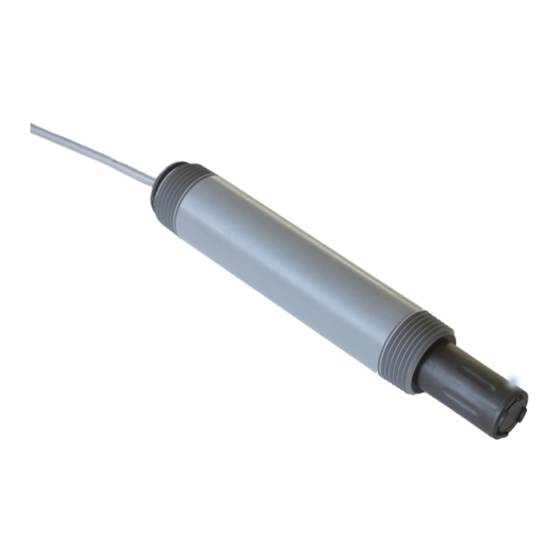
- Page 1 AquaMetrix AM-ODO-TX Optical Dissolved Oxygen Probe Installation and Operation Manual ODO-TX Operating Manual N116-155 rev 1.0...
-
Page 2: Table Of Contents
Contents Introduction ............................3 Safety ..............................3 Getting Started ............................4 ODO-TX Sensor and Specifications......................4 4.1. System Description ........................4 4.2. Specifications ..........................5 4.3. Dimensions ............................ 6 4.4. Connections to power supply and controller ................6 Installation ............................7 Communication ............................. -
Page 3: Introduction
11. Troubleshooting ..........................23 12. Disposal ............................... 23 13. Contact ..............................23 Appendix A: Dissolved Oxygen Equations ....................25 Appendix B: Commkit ..........................27 Appendix C: Definitions ..........................32 1. Introduction The AM-ODO is one of the most compact, durable, and easiest to use dissolved oxygen sensors on the market. -
Page 4: Getting Started
The probe should only be installed, stored and serviced in the manner described in this manual. Improper handling may result in damage to the unit and surrounding equipment and may void the warranty. 3. Getting Started 1. A temperature sensor is built into the probe body, close to the sensor cap. It should be completely immersed in the sample when taking measurements. -
Page 5: Specifications
4.2. Specifications Probe Parameters Parameters Optical Dissolved Oxygen Sensor Data Transmission Analog (4-20mA), RS485, Modbus Range, DO 0-60 mg/L; 0-600% Saturation +/- 0.1 mg/L (0-20 mg/L) Accuracy, DO +/-2% (20-60 mg/L) Resolution, DO 0.01 mg/L Response Time, Cap T63<5s, T90<45s, T95<60s Units, DO mg/L, ppm, % saturation Range, Temp. -
Page 6: Dimensions
Environmental Pressure 150 psi from 0° to 50°C Depth 100 m (328 ft) @ 25°C Operating Temperature (non-freezing) -5°C to 50°C (23°F to 122°F) Storage Temperature -40°C to 65°C (-40°F to 149°F) Alcohols >5%; hydrogen peroxide > 3%; sodium hypochlorite (commercial bleach) >... -
Page 7: Installation
5. Installation The AM-ODO-TX can be connected to an AquaMetrix AM-2300 controller or any PLC. The probe can output either a single output or dual outputs. As factory default, the ODO-TX comes wired as such: Using the RS485 connection the user can change the default analog outputs from the following selections: An optional configuration outputs the temperature or pressure as a second parameter. -
Page 8: Communication
Figure 2- Wiring AM-ODO-TX to an AM-2252 or a PLC with an external power supply 6. Communication 6.1. Analog The standard mapping for the ODO-TX analog output is: Output Output Parameter 20mA Analog 1 Dissolved Oxygen (Percent Saturation) Analog 2 Dissolved Oxygen (concentration) The Two (2) Analog outputs can be remapped at the factory and by the customer Output Parameter... -
Page 9: Modbus
6.2. Modbus 6.2.1. Common Registers Register Size Mode & Access Data Type Description Level (R/W) 9001 ushort Device ID = 36 or 37 (analog model) 9002 ulong Device serial number 9004 time Manufacture date 6.2.2. Sensor Status Registers Register Size Mode &... -
Page 10: Device Specific Registers
6.2.4. Device Specific Registers Mode & Access Register Size Data Type Description Level (R/W) Dissolved Oxygen Concentration 0038 2 R1 float Measured value, Co 0040 1 R1 ushort Parameter ID = 20 Units ID 0041 1 R1/W2 ushort 117 = mg/L (default) 118 = ug/L Data quality ID (See 0042... - Page 11 Temperature 0046 2 R1 float Measured value 0048 1 R1 ushort Parameter ID = 1 Units ID 0049 1 R1/W2 ushort 1= °C (default) 2= °F 0050 1 R1 ushort Data quality ID Offline sentinel 0051 2 R1/W3 float value (default = 0.0) Available units = 0053 1 R1...
- Page 12 Oxygen Partial Pressure 0062 2 R1 float Measured value Parameter ID = 2 0064 1 R1 ushort (pressure) 0065 1 R1/W2 ushort Units ID 26 = torr (default) 0066 1 R1 ushort Data quality ID Offline sentinel 0067 2 R1/W3 float value (default = 0.0) Available Units =...
-
Page 13: Calibration Registers
6.2.5. Calibration Registers Register Size Mode & Access Data Type Description Level (R/W) 0118 2 R1/W3 float Live salinity value (PSU) 0120 2 R1/W3 float Default salinity value (PSU, default = 0.0) 0122 2 R1/W3 float Live barometric pressure (mbar) 0124 2 R1/W3 float... - Page 14 0130 2 R1/W3 float 100% saturation salinity value (PSU) 0132 2 R1/W3 float 100% saturation barometric pressure (mbar) 0134 2 R1/W3 float 0% saturation calibration reading (mg/L) 0136 2 R1/W3 float 0% saturation temperature reading (°C) 0138 2 R1/W3 float Calibration slope (default = 1.0) 0140...
-
Page 15: Sensor Health Table
6.2.6. Sensor Health Table The instrument records a data quality ID between 0 and 7 with each reading. This ID indicates whether errors occurred during the reading. It is stored in the instrument’s data quality register. See the table below for details. Abbreviation Data Quality Text... - Page 16 4 Sensor Warm-up Sensor is warming up, sentinel value supplied. 5 Sensor Warning Parameter measured but does not meet normal quality criteria. The sensor has sustained moderate damage, or the recommended lifespan has been reached. 6 Sensor Calibrating Sensor is calibrating, calibration value supplied.
-
Page 17: Calibration
7. Calibration Connect the ODO-TX to a computer using the RS485 connection and open Commkit communication. Alternately, connect the ODO-TX to an appropriate controller or PLC with calibration capability. If using a PLC or controller to calibrate, refer to your controller manual. You can either perform a one-point or two-point calibration as noted below. -
Page 18: Maintenance
8. Maintenance 8.1. Cleaning Probe maintenance includes cleaning the sensor cap, as well as the proper conditioning, preparation, and storage of the test system. With the membrane sensor cap and guard cap installed on ODO-TX, gently scrub the probe with a soft-bristled brush or nylon dish scrubber. Use Alconox or similar cleaning solution to remove grease or other matter. -
Page 19: Spare Parts
9. Spare Parts Part # Description AM-ODO-TX-CAP ODO-TX-Replacement Sensor Cap Sensor Cap Storage Prior to installation—Store in factory supplied container. Installed—Store in the calibration chamber with the storage cap attached and a few drops of clean water. 10. Accessories Part # Description AM-ODO-TX-CAL Calibration Cap... -
Page 20: Mounting
2. Place the sponge wafer in the bottom of the calibration chamber and saturate with approximately 10 mL water. 3. Gently dry the instrument and sensing material with a paper towel, making sure there is no water or debris on the instrument or on the sensing surface. 4. -
Page 21: Inline Mounting With The Am-Tee-5
To mount the ODO-TX on the AM-ARM-5: Guide the probe cable from the 1” NPT fitting side from the front end of the submersion arm all the way through and back out the back. Loosen the strain relief, thread the cable through, and tighten it. Slide the aluminum wire mounting bracket onto the probe. - Page 22 To mount the ODO-TX probe in the AM-TEE-5: 1. Insert split ring and nut aver the sensor. 2. Screw the ODO-TX into the 1” Insert bushing. 3. Slide the bushing assembly into the tee and screw on the compression nut. Install lock nut into a groove to keep the nut attached to the assembly.
-
Page 23: Troubleshooting
Please contact us at support@wateranalytics.net or call us at 978-749-9949 This manual contains confidential and copyrighted information owned by Water Analytics. The contents of this document may not be reproduced, photocopied, or translated into another language without the ODO-TX Operating Manual... - Page 24 Water Analytics. RDO® is a registered trademark of In-Situ® Inc., Fort Collins, CO USA. Water Analytics provides this material as-is and makes no warranties, express or implied, regarding its suitability for any specific purpose. Water Analytics shall not be held responsible for any errors or damages, whether incidental or consequential, arising from the use or performance of this material.
-
Page 25: Appendix A: Dissolved Oxygen Equations
Appendix A: Dissolved Oxygen Equations Dissolved Oxygen Concentration DO concentration is internally calculated in mg/L. Conversion to other units is as follows: ODO-TX Operating Manual N116-155 rev 1.0... - Page 26 ODO-TX Operating Manual N116-155 rev 1.0...
-
Page 27: Appendix B: Commkit
Appendix B: Commkit 1. About CommKit Comm Kit software allows you to configure and calibrate your dissolved oxygen probe on a Windows PC. A link for installation can be found on our website or by using the QR code on your sensor. 2. - Page 28 e. When a connection is successful, Comm Kit displays live readings from the instrument. Communication tab to change Modbus or 4-20 mA settings. ODO-TX Operating Manual N116-155 rev 1.0...
- Page 29 4. Sensor Set up ODO-TX Operating Manual N116-155 rev 1.0...
- Page 30 5. Probe Info Screen ODO-TX Operating Manual N116-155 rev 1.0...
- Page 31 6. Saving Live readings to Spreadsheet To save live readings to a spreadsheet, first select the parameters you are looking to save and then click the “Save live data to file” checkbox. Once you have saved the log’s location and you’re ready to begin recording data, press the Start button.
-
Page 32: Appendix C: Definitions
Appendix C: Definitions Live Salinity Value The live salinity value is used to correct the oxygen concentration value for salinity. Values must be written in Practical Salinity Units (PSU) in the range 0 to 42 PSU. This is not a measured parameter. Default Salinity Value The default salinity value is loaded into the live salinity value register when power is first applied to the probe. - Page 33 These values represent the slope and offset that will be applied to the raw concentration reading from the sensor to generate the final values reported by the sensor parameters. These registers may be written independently of the normal internal calibration procedure. Entering Calibration Registers The sensor is calibrated using the following procedure.
Need help?
Do you have a question about the AquaMetrix AM-ODO-TX and is the answer not in the manual?
Questions and answers