
Related Manuals for Ashley Signature DESIGN P782-772


Summary of Contents for Ashley Signature DESIGN P782-772
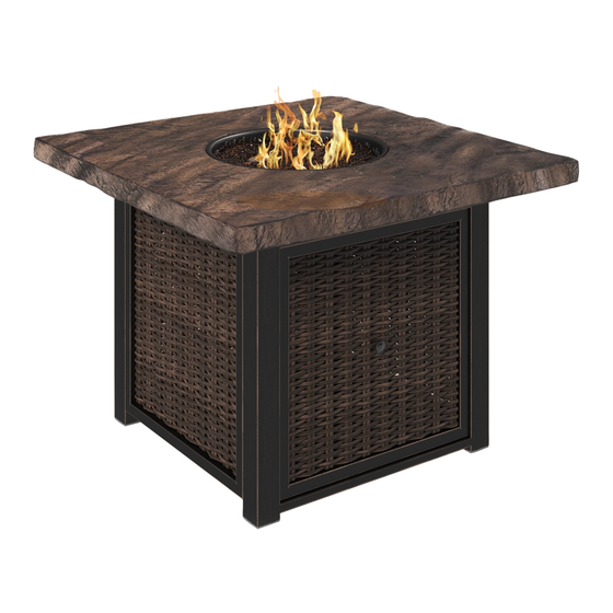
- Page 1 Outdoor Square Fire Pit Table User Guide ITEM#: P78 2-772 Product has been CSA tested and certified. THIS PRODUCTWAS MANUFACTURED BY JIAXING HERO IMP & EXP CO,.LTD FOR ASHLEY FURNITURE INDUSTRIES, INC. Page 1 of 43 P782-772...
- Page 2 IMPORTANT, FAILURE TO CAREFULLY READ, UNDERSTAND AND FOLLOW EVERY PART OF THIS DOCUMENT MAY RESULT IN PROPERTY DAMAGE, SERIOUS BODILY INJURY OR DEATH ASSEMBLY INSTRUCTIONS Installer: Leave these instructions with consumer. C S A Model 7 0 1 5 1 9 5 0 PA020-772 Consumer: Keep these instructions for future reference SAFETY INFORM ATION...
- Page 3 SAFETY INFOR MATION DANGER DANGER EXPLOSION-FIRE HAZARD CARBON MONOXIDE HAZARD This fire pit is a combustion appliance. All combustion Keep solid combustibles, such as building materials, appliances produce carbon monoxide (CO) during the paper of cardboard, a safe distance away from the combustion process.
-
Page 4: Table Of Contents
TABLE OF CONTENTS 1. Important Safety Information ..........5 2. Information about Propane ..........7 3. Specifications ................7 4. Parts List ..................8 5. Installation ................... 9 6. Natural Gas Conversion ............13 7. Batteries ..................14 8. Lighting Instructions ..............15 9. -
Page 5: Important Safety Information
IMPORTANT SAFETY INFORMATION The installation must conform with local codes or, in the absence of all applicable local codes, including, without limitation, with the National Fu el Gas Code, ANSI Z223.1/NFP A 54; International Fuel Gas Code; Natural Gas and Propane Installation Code, CSA B149.1; or Propane Storage and Handling Code, B149.2, as applicable. - Page 6 Keep the fuel supply hose away from any heated surfaces. If you have any questions regarding the use of this unit, or find that your fire pit unit needs service, please contact Ashley Furniture Industries at the below number. 1 (800) 477-2222 Customer Service.
-
Page 7: Specifications
IMPORTANT SAFETY INFORMATION ABOUT PROPANE (LP) GAS A self-contained LP-gas cylinder for use with this appliance must have a capacity of 20 lbs. and must be equipped with a Type 1 connector and an OP D (overfill protection device). See Figure 1. The LP-gas supply cylinder to be used must be constructed and marked in accordance with the specification for LP- gas cylinders of the U.S. - Page 8 PARTS IDENTIFICATION LIST Item Description Burner Cover e W/Wicker Left Side Fram e W/Wicker Right Side Fram e W/Wicker Door Fram e W/Wicker Back Fram Front Leg Frame Cylinder Holder Support Left Leg Right Leg Support bar 1/4 in x 20 mm Bolt 1/4 in x 30 mm Bolt 1/4 in x 60 mm Bolt Flat Washer...
-
Page 9: Installation
INSTALLATION 1.Attach the Front leg frame(G),Right leg(L),Left leg(K) to Table top(B)using 4pcs of 1/4 in X20mm Bolt(N), 4pcs of Lock Washer(T) and 4 pcs of Flat Washer (S) by Allen Wrench(U). 2.Attach the Right Side Frame (D) to Front leg frame(G), Right Leg(L) using 4pcs of 1/4 in X60mm Bolt(R), 4pcs of Lock Washer(T) and 4pcs of Flat Washer(S) U R T S... - Page 10 INSTALLATION 4.Attach the Support bar(M) to the Cylinder Holder(H) using 4pcs of 1/4 in X30mm Bolt(P),4pcs of Lock Washer(T) and 4 pcs of Flat Washer (S)by Allen Wrench(U).Then attach the Cylinder Holder(H)to Right Side Frame (D) And Left Side Frame (C)also using 4pcs of 1/4 in X30mm Bolt(P),4pcs of Lock Washer(T) and 4 pcs of Flat Washer (S)by Allen Wrench(U).
- Page 11 INSTALLATION 7.Pour the box of Fire Glass(Y)into the fire pit table top(B) around. DANGER To ensure proper function, the guard on this burner should be free of fire glass at all times. 8.Make sure the control knob is in the “OFF” position.
-
Page 12: Natural Gas Conversion
INSTALLATION PRESSURE RELIEF VALVE CYLINDER VALVE BLACK COUPLING NUT BLEED-OFF turn clockwise to connect VALVE turn clockwise REGULATOR to reseal NATURAL GAS CONVERSION WARNING If the information in this manual is not followed exactly, a fi re or IMPORTANT explosion may result causing property damage personal injury SAVE THESE INSTRUCTIONS or loss of life. -
Page 13: Lighting Instructions
Prior to turning gas on and attempting to light the appliance, make sure the appliance is outside, in a well ventilated area and free of any debris and is not in contact with or near any people, animals, materials or structures. Failure to adhere to the above instruction may result in property damage, serious bodily injury or death. -
Page 14: Maintenance
MAINTENANCE • Before performing any maintenance always disconnect propane gas tank. • Keep the heating item free and clear from combustible materials. • Visually inspect burner for obstructions and keep tank enclosure free and clear from debris. • Use a soft brush to get rid of the mild stains, loose dirt and soil after the burner is completely cooled down. - Page 15 2#%) %Q (#,#*'()20 1-)0 %) '00S ;(S0#)20 P782-772 Page 15 sur 43...
- Page 16 C S A Model 7 0 1 5 1 9 5 0 " "# !$ PA020-772 "# !$ -$" " !$ " ! " " " " " " #$%#A2) 2$) *#(2'(#1$ );(0&+)+)$( %'$8)0)2*) " A2# *# ),,) $")*( :'* %5#(%) :1200'#( &'2*)0 %)* ?,)**20)* "...
- Page 17 " * +!,- *, . + /0*, *, -1 +, ) 41-)0 )*( 2$ '::'0)#, %) &1+?2*(#1$ 12* ,)* '0%)0 %)* &1+?2*(#?,)* *1,#%* (),* A2) %)* '::'0)#,* %) &1+?2*(#1$ :01%2#*)$( ,) +1$1;-%) %) +'(%0#'2; %) &1$*2(02&(#1$ ,) :':#)0 %) &'0(1$ 2$) &'0?1$) )$ &120* %) &1+?2*(#1$ ) :01%2#( )*(...
- Page 18 1$*#8$)* %) %&20#(% +:10('$()* $410+'(#1$ ' :01:1* %) 01:'$) < :%#&'(#1$* #*() %)* #)&)* < I $*(',,'(#1$ 1$5)0*#1$ %) '/ '(20), '(()0#)* K $*(02&(#1$* %" ,,2+'8) '#$()$'$&) < 2#%) %) %:'$$'8) < P782-772 Page 18 sur 43...
- Page 19 "#$*(',,'(#1$ %1#( &1$410+)0 '2; &1%)* ,1&'2; 12 %'$* ,"'?*)$&) %) (12* ,)* &1%)* ,1&'2; '::,#&'?,)* - &1+:0#* *'$* ,#+#() '5)& '(#1$', 2 ), < !@ IC9 $()0$'(#1$', 1%)9 '(20', '* '$% 01:'$) $*(',,'(#1$ !C !9 12 01:'$) (10'8) '$% '$%,#$8 &1++) '::,#&'?,) "'::'0)#, )( ,' 5'$$) %) 8'/ :0#$&#:',) %) ,"'::'0)#, %1#5)$( &(0) %%&1$$)&(%* %) *-*()+) %) (2-'2'8) %"',#+)$('(#1$ %) 8'/ )$ &120* %) ()*( %) :0)**20) %) &) *-*()+) ' ,' :0)**20) %) ()*( ,#+#(%) '!@ :*# <...
- Page 20 , $")*( :'* 4 %"2(#,#*)0 &) :01%2#( :120 %) ?2( *'24 %%&0#( %'$* &) %1&2+)$( - &1+:0#* *'$* ,#+#() ,' &2#*#$) D ) 0%82,'()20 %) :0)**#1$ %) :01:'$) 4120$# '5)& &)( '::'0)#, %1#( &(0) 2(#,#*% ) 0%82,'()20 )*( 0%8,% :120 2$) :0)**#1$ %) *10(#) %) !! :12&)* %) &1,1$$) %")'2 )( '::'0)#, %) 8'/ );()0$) $")*( :'* :120 ,"#$*(',,'(#1$ %'$* 12 *20 %)* 5%.#&2,)* )(@12 ?'()'2;...
- Page 21 > $) ?12()#,,) %) 8'/ '2(1$1+) :120 ,Q2*'8) '5)& &)( '::'0)#, %1#( '51#0 2$) &':'&#(S %) ( %1#( [(0) SA2#:S %Q2$ &1$$)&()20 %) -:) ! )( 2$ '::'0)#, %) :01()&(#1$ *200)+:,# "1#0 #820) ! ! " # & ) *-*(V+) %Q',#+)$('(#1$ %) ?12()#,,) %1#( [(0) '00'$8) :120 ,Q)$,V5)+)$( %) 5':)20 ' ?12()#,,) 2(#,#*S) %1#( #$&,20) 2$ &1, :120 :01(S8)0 ,' 5'$$) %) ?12()#,,) )( '::'0)#, %1#( [(0) 2(#,#*S *)2,)+)$( X ,Q);(S0#)20 %'$* 2$ )*:'&) ?#)$ 5)$(#,S )( $) %1#( :'* [(0) 2(#,#*S %'$* 2$ ?\(#+)$( 8'0'8) 12 (12( '2(0) )*:'&)
- Page 22 1" 1 & # !- !$ Couvercle du brûleur Dessus Cadre côté gauche avec Joint à recouvrement Cadre côté droit avec joint à recouvrement Cadre de porte avec Joint à recouvrement Cadre arrière avec joint à recouvrement Cadre patte avant Porte Cylindre Support Patte gauche...
- Page 23 INSTALLATION 1. Fixez le cadre de la patte Avant (G), la patte Droite (L), la patte Gauche (K) au plateau de la Table (B) en utilisant 4 pcs Boulons ¼ in x20mm (N), 4 pcs Rondelle de Blocage (T) et 4 pcs Rondelle Plate (S) avec la Clé...
- Page 24 INSTALLATION 4. Fixez la barre de Support (M) au Porte Cylindre (H) en utilisant 4 pcs Boulons ¼ in x30mm (P), 4 pcs Rondelle de Blocage (R) et 4 pcs Rondelle Plate (S) avec la Clé Allen (U). Puis attachez le Porte Cylindre (H) au Cadre Côté...
- Page 25 INSTALLATION 7. Versez la boite de (Y) dans le dessus du foyer (B). Assurez-vous que le bouton de commande soit sur la position “ARRÊT”. Dévissez le capuchon du bouton poussoir sur le module d’allumage situé sur le panneau de contrôle pour accéder au compartiment à...
- Page 26 P782-772 Page 26 sur 43...
- Page 27 " " " " & " " " $" "& #0) %)* #$*(02&(#1$* '5'$( ,Q',,2+'8) ) ?12(1$ %) &1++'$%) %1#( [(0) X ,' :1*#(#1$ ^ < 1$$)&()0 ,' ?12()#,,) %) :01:'$) "1#0 '$2), 1250#0 ,' 5'$$) %) ,' ?12()#,,) 12**)0 )( +)((0) ,) ?12(1$ %) &1++'$%) )$ *)$* #$5)0*) %)* '#82#,,)* %Q2$) +1$(0) X ^ ::2-)0 0S:S(#(#5)+)$( *20 ,) ?12(1$ ',,2+)20 :120 ',,2+)0 ,) ?0Y,)20 ),\&.)0 ,) ?12(1$ %) &1++'$%) ':0V* CI *)&1$%)* # ,Q',,2+'8) $Q' :'* ,#)2 %'$* CI *)&1$%)* :12**)0 )( +)((0) ,) ?12(1$ %) &1++'$%)
- Page 28 MAINTENANCE GUIDE DE DEPANNAGE Il est recommandé que vous contactiez un technicien de service qualifié si vous pensez que l’appareil ne fonctionne pas correctement. û é é à é é ’ â é ’ é ’é ’ é é ’ ’...
- Page 29 '$2', %), 2*2'0#1 %) 418'(' &2'%0'%' );()0#10 G U A R D A E S T A S I N S T R U C C I O N E S JK 7JJ _8#$'...
- Page 30 1 1/ C S A Model 7 0 1 5 1 9 5 0 &, #+ ($ ( < "##!$ #$ "& PA020-772 "&!($ "##!$ #! ." " ' ) !*+ , '0' 2*1 &1$ ,#?0'* B8 &#,#$%01 %) :01:'$1 &1$ (#:1 ! &1$);#1$ 1 :'0' 2*1 &1$ 8'* $'(20', %)*:2)* %) ,' &1$5)0*#1$ B#( )* #$*(','%1 %)?) *)0 #$*(','%1 :014)*#1$',+)$() ('+?#%$ ),...
- Page 31 ) !*+ , '$()$8' ,1* &1+?2*(#?,)* *`,#%1* (',)* &1+1 +'()0#',)* %) *() :1/1 %) 42)81 )* 2$ ':'0'(1 %) &1+?2*(#` $ &1$*(02&&#`$ :':), %) &'0(`$ ' 2$' %#*('$&#' *)820' %) ,' 1%1* ,1* ':'0'(1* %) &1+?2*(#` $:01%2&)$ +1$` ;#%1%) &'0?1$1 %20'$() ), :01&)*1 %) .182)0' &1+1 *) 0)&1+#)$%' )$ ,'* #$*(02&$)* &1+?2*(#` $ *() :01%2&(1 )*(_%#*)b '%1:'0'...
- Page 32 ! $410+'&#` $%) )820#%'% +:10('$() <I $410+'&#` $*1?0) ), 01:'$1 <J < *:)#&'$)* <K #*(' %) :#)/'* < I $*(','&#`$ 1$5)0*#`$ %) 8'* $'(20', '()0a'* K $*(02&$)* %) #,2+#$'&#`$ '$()$#+#)$(1 2a'%) *1,2&#`$ %) :01?,)+'* JK 7JJ _8#$'...
- Page 33 ' #$*(','&#`$ %)?) &2+:,#0 &1$ ,1* &`%#81* ,1&',)* 1 )$ '2*)$&#' %) &`%#81* ,1&',)* %) (1%1* ,1* &`%#81* ,1&',)* ':,#&'?,)* #$&,2-)$%1 *#$ ,#+#('&#`$ &1$ ), `%#81 '$', %) 8'* &1+?2*(#?,) < !@ IC9 `%#81 $()0$'$', %) 8'* &1+?2*(#?,) 9 `%#81 %) #$*(','&#`$ %) 8'* $'(20', - :01:'$1 !C ! 9 1 :01:'$1 ',+'&)$'+#)$(1 - +'$)61 %) &`%#81...
- Page 34 * *)8201 2*'0 )*() :01%2&(1 :'0' &2',A2#)0 :01:`*#(1 );&):(1 &1+1 *) %)*&0#?) )$ )*() %1&2+)$(1 #$&,2-)$%1 *#$ ,#+#('&#`$ ,' &1&#$' # "#!Q ), 0)82,'%10 %) :0)*#`$ %) 8'* :01:'$1 *2+#$#*(0'%1 &1$ )*() ':'0'(1 %)?) *)0 2(#,#/'%1 *() 0)82,'%10 )*(_ 4#6'%1 :'0' 2$' :0)*#`$ %) *',#%' %) !! :2,8'%'* %) &1,2+$' %) '82' *() ':'0'(1 %) 8'* ', '#0) ,#?0) $1 )*(_ %)*(#$'%1 ' *)0 #$*(','%1 )$ 5).a&2,1* %) 0)&0)1 - @ 1 ?'0&1* $()* %) &'%' 2*1 %) )*() ':'0'(1 %) 8'* '?0' ), :01:'$1 ,aA2#%1...
- Page 35 > , &#,#$%01 %) *2+#$#*(01 %) '* :'0' 2*1 &1$ )*() ':'0'(1 %)?) ()$)0 2$' &':'&#%'% %) %)?) )*('0 )A2#:'%1 &1$ 2$ &1$)&(10 %) (#:1 ! - 2$' :01()&&#`$ &1$(0' *1?0),,)$'%1 %#*:1*#(#51 ")0 #820' ! , &#,#$%01 %) *2+#$#*(01 %) '* :'0' *)0 2(#,#/'%1 %)?) *)0 &1$*(02#%1 - +'0&'%1* %) &1$410+#%'% &1$ ), :,#)81 %) &1$%#$)* :'0' &#,#$%01* %) 8'* ), ):'0('+)$(1 %)
- Page 36 #820' ! $(0'%' < @ .0 0)*#`$ %), !! :2,8'%'* %) &1,2+$' %) '82' 0)82,'%10 %) '* '(20', J :2,8'%'* %) &1,2+$' %) '82' a$#+1 2(10#/'$)* ' '%1*D C#$ @ E!&+ 1:D J #$ @ !K< &+ ,'* *2:)04#&#)* JK 7JJ _8#$'...
- Page 37 ( & # !-#!. !( ( Cubierta del quemador Parte superior Bastidor del lado izquierdo de mimbre Bastidor del lado derecho de mimbre Bastidor de la puerta de mimbre re Bastidor trasero de mimbre Bastidor de la pata delantera Adaptador del cilindro Soporte Pata izquierda Pata derecha...
- Page 38 1. Fije el bastidor de la pata delantera (G), pata derecha (L) y pata izquierda (K) al tablero superior (B) usando 4 tornillos de 1/4 pulg. x 20 mm (N), 4 arandelas de seguridad (T) y 4 arandelas planas (S) mediante una llave Allen (U). 2.
- Page 39 4. Fije la barra de soporte (M) al adaptador del cilindro (H) usando 4 tornillos de 1/4 pulg. x 30 mm (P), 4 arandelas de seguridad (T) y 4 arandelas planas (S) mediante una llave Allen (U). A continuación, fije el adaptador del cilindro (H) al bastidor del lado derecho (D) y al bastidor del lado izquierdo (C) usando también 4 tornillos de 1/4 pulg.
- Page 40 7. Vierta la caja de (Y) en el tablero superior del fogón (B) y alrededor. Asegúrese de que la perilla de control está en la posición «OFF». Desatornille la tapa del pulsador del módulo de ignición ubicado en el panel de control para acceder al compartimento de la batería (W). El módulo de ignición requiere una pila de tamaño AAA (W).
- Page 41 JK 7JJ _8#$'...
- Page 42 ( =" J ." " ! ( 7 !9 ( #" ="! !("$/ 7 $ # $ #$ - !& / & "# " ! # # ( ! #"&- !&! "##!$ -" ( " ( O$ - $-! ( (/ #$ -$ &"...
- Page 43 MANTENIMIENTO GUÍA DE SOLUCIÓN DE PROBLEMAS PROBLEMA CAUSA REMEDIO La falta de ox geno Termopar no está en llamas JK 7JJ _8#$'...
Need help?
Do you have a question about the Signature DESIGN P782-772 and is the answer not in the manual?
Questions and answers