
Related Manuals for APPLIED ACOUSTICS CSP-CSPD-8000/2


Summary of Contents for APPLIED ACOUSTICS CSP-CSPD-8000/2
- Page 1 CAPACITOR CHARGING UNIT CSP-CSPD-8000/2 MODELS COVERED IN THIS MANUAL: CSP-D 2400 CSP-D 1200 CSP-D 700 ISSUE 2 JUNE 08...
- Page 2 CSP-CSPD-8000/2- Section 1 Page 2 of 30...
- Page 3 OPERATION MANUAL Section 1 CSP-CSPD-8000/2- Section 1 Page 3 of 30...
- Page 4 CONTENTS PAGE CSP-CSPD-8000/2- Section 1 Page 4 of 30...
-
Page 5: Table Of Contents
Enviormental Considerations ......9 Introduction ............. 10 Installation ............11 Operation ............18 Operator Controls and Indicators ....23 Specifications ........... 28 CSP-CSPD-8000/2- Section 1 Page 5 of 30... - Page 6 CSP-CSPD-8000/2- Section 1 Page 6 of 30...
- Page 7 CSP-CSPD-8000/2- Section 1 Page 7 of 30...
- Page 8 CSP-CSPD-8000/2- Section 1 Page 8 of 30...
- Page 9 This web site refers to UK waters and relates to air guns as the sound source (in many ways different to a sparker or boomer), but should serve as a useful guide nonetheless. CSP-CSPD-8000/2- Section 1 Page 9 of 30...
-
Page 10: Introduction
This maybe effective in certain instances where more penetration is required. The CSP-Ds monitor the output of the system for open circuit fault conditions and over current fault conditions, limited to approx 5000A. CSP-CSPD-8000/2- Section 1 Page 10 of 30... -
Page 11: Installation
(ie bringing the unit into a warm room from a cold area) and allow the fans to operate for 10 - 15 minutes before switching on the high voltage. CSP-CSPD-8000/2- Section 1 Page 11 of 30... - Page 12 This manual is supplied in three parts: Section 1 Basic operation information details. Section 2 For manufacturer trained technicians only provides troubleshooting advice, schematics circuit descriptions. Section 3 Provides block and circuit diagrams. CSP-CSPD-8000/2- Section 1 Page 12 of 30...
-
Page 13: Operation
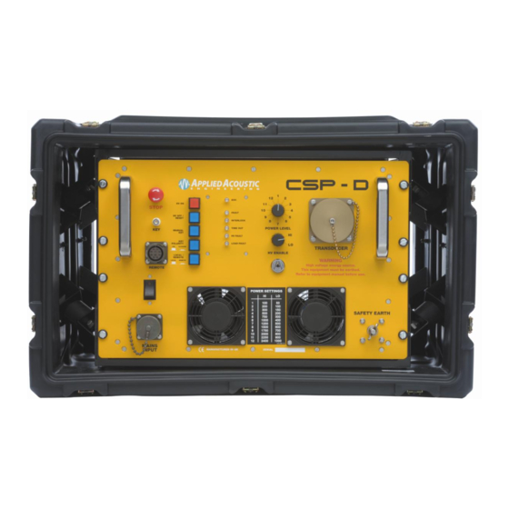
A weight will also be necessary to keep the wire submerged when the vessel is underway. CSP-CSPD-8000/2- Section 1 Page 13 of 30... - Page 14 THE CSP-D FRONT PANEL. The junction box is fitted with a microswitch which is connected to sense pins in the HV plug, ie deactivating the high voltage charger if the lid is removed and the ‘INTERLOCK’ light will illuminate. CSP-CSPD-8000/2- Section 1 Page 14 of 30...
- Page 15 20% to 98%, thus allowing 100J 3pps operation from a 500 VA generator. Note that it can take up to 16 samples for the charge rate to be set to the correct amount. AC POWER REQUIREMENTS CSP-CSPD-8000/2- Section 1 Page 15 of 30...
- Page 16 ‘specifications’ The above tables denote the ability of the charger to perform under certain line voltage conditions, and not the complete system. We do not recommend operating the CSP-D units below the minimum voltages listed in the specification section of this manual. CSP-CSPD-8000/2- Section 1 Page 16 of 30...
- Page 17 OK. The remote also has a FAULT LED, as well as high voltage ON and high voltage OFF indicators. LOCAL Operation indicated by LED on – Switch OUT. REMOTE Opersation indicated by LED out – switch IN CSP-CSPD-8000/2- Section 1 Page 17 of 30...
- Page 18 For example, at 300J / shot the CSP-D models will run at 5 PPS. At 1200J (or 1250J), the CSP-D 1200 and 2400 will operate at 1 pulse per second, with a little in reserve. CSP-CSPD-8000/2- Section 1 Page 18 of 30...
- Page 19 2400 1000 Items marked in red are not suitable for a single boomer. The blue column is unlikely to be suitable for sparker applications. Operation of the CSP-D with a boomer sound source. CSP-CSPD-8000/2- Section 1 Page 19 of 30...
- Page 20 – to date- been tested with any other type. Ensure that the energy and repetition rate do not over drive the sound source ! (boomer plate - check the boomer plate manual). CSP-CSPD-8000/2- Section 1 Page 20 of 30...
- Page 21 CSP-D units in the workshop to avoid ‘water based dummy loads’ such as dustbins full of salt water etc! Please check with other sparker manufacturers whether their sparkers are compatible with the specifications laid out in this manual. CSP-CSPD-8000/2- Section 1 Page 21 of 30...
- Page 22 CSP-CSPD-8000/2- Section 1 Page 22 of 30...
-
Page 23: Operator Controls And Indicators
Note that the unit can be switched off from the front panel and the remote at any time. CHARGE RATE switch (Located on rear panel) As previously described, this switch selects the AVIP circuitry or full charge. Recommended position : Out (AVIP Engaged) CSP-CSPD-8000/2- Section 1 Page 23 of 30... - Page 24 LOAD FAULT Indicator Indicates an HV Output over current or open circuit condition. The indicator will be illuminated together with the HV OFF LED for 10secs before reseting. CSP-CSPD-8000/2- Section 1 Page 24 of 30...
- Page 25 The rear panel of the units has 2 fold-down handles to ease installation, and also has 2 fan filters for the cooling air intake. These filters should be periodically cleaned to ensure maximum air flow. This can be done with a small stiff brush. CSP-CSPD-8000/2- Section 1 Page 25 of 30...
- Page 26 Despite being heavily insulated, the HV cable should not be touched or held when the unit is operating. The load should always be in the water before operation. Crewmembers should be made aware of these facts during mobilisations. CSP-CSPD-8000/2- Section 1 Page 26 of 30...
-
Page 27: Specifications
: A current sensor ensures that the unit shuts down beyond approximately 6000 Amps although the thyristor module can exceed this. Remote : 10 way amphenol. Earth : M8 stainless stud on front panel. . 110 BOUT ENERATOR ELECTION VOLT VERSIONS ARE AVAILABLE CSP-CSPD-8000/2- Section 1 Page 27 of 30... - Page 28 : For storage and transportation. Foam lined. Field Spares Kit : For trained technicians only. For servicing units in the field. Although correct at time of printing, these specifications are subject to change without notice. CSP-CSPD-8000/2- Section 1 Page 28 of 30...
- Page 29 CSP-CSPD-8000/2- Section 1 Page 29 of 30...
- Page 30 CSP-CSPD-8000/2- Section 1 Page 30 of 30...
Need help?
Do you have a question about the CSP-CSPD-8000/2 and is the answer not in the manual?
Questions and answers