Table of Contents
Advertisement
Quick Links
Advertisement
Table of Contents
Troubleshooting

Related Manuals for APPLIED ACOUSTICS CSP-N Series


Summary of Contents for APPLIED ACOUSTICS CSP-N Series
- Page 1 CSPN Capacitor Charging Unit Operation Manual...
-
Page 2: Revision History
CSPN Capacitor Charging Unit Operation Manual CSP-CSPN-8000/1 __________________________________________________________________________________________________________ Revision History Change Issue Reason for change Date CSPN 2400 Changes Non AAE Sound Source Guidelines added Maintenance Checklist added 18/08/15 Schematics updated HVJ3001 diagrams updated __________________________________________________________________________________________________________ Page 2 of 63... -
Page 3: Table Of Contents
CSPN Capacitor Charging Unit Operation Manual CSP-CSPN-8000/1 __________________________________________________________________________________________________________ Table of Contents REVISION HISTORY ............................2 SECTION 1 - OPERATIONAL .......................... 7 1.1. ENVIRONMENTAL CONSIDERATIONS ....................7 1.2. INTRODUCTION ............................8 1.3. INSTALLATION ............................9 ... - Page 4 CSPN Capacitor Charging Unit Operation Manual CSP-CSPN-8000/1 __________________________________________________________________________________________________________ 1.6. REAR PANEL ............................21 ................................21 USES ........................... 21 HARGE WITCH ..............................21 ILTERS 1.7. PRODUCT RECYCLING / DISPOSAL ....................22 1.8. SPECIFICATIONS............................ 23 ...
- Page 5 CSPN Capacitor Charging Unit Operation Manual CSP-CSPN-8000/1 __________________________________________________________________________________________________________ 4.4. HVJ3001 INTERCONNECTIONS ......................62 4.5. HVJ3001 JUNCTION BOX INTERLOCK WIRING .................. 62 Thank you for choosing Applied Acoustic Engineering as one of your subsea equipment suppliers. We hope you experience many years of reliable operational use from our products. If you do encounter any technical issues with any of our products then please don’t hesitate to contact our Technical Team via the following methods.
- Page 6 CSPN Capacitor Charging Unit Operation Manual CSP-CSPN-8000/1 __________________________________________________________________________________________________________ WARNING HIS EQUIPMENT CONTAINS LETHAL VOLTAGES AND MUST BE EARTHED AT ALL TIMES NSURE ADEQUATE SAFETY PROCEDURES ARE EMPLOYED Information in this manual is copyright 1993 – 2015, Applied Acoustic Engineering Ltd. This manual is loaned without other consideration than the agreement and condition that it is not to be reproduced, copied or otherwise disposed of directly, and is not to be used in whole or in part to assist in or to furnish any information for the making of drawings, prints, apparatus or parts...
-
Page 7: Section 1 - Operational
CSPN Capacitor Charging Unit Operation Manual CSP-CSPN-8000/1 __________________________________________________________________________________________________________ Section 1 - OPERATIONAL 1.1. Environmental Considerations Seismic Sound Sources and Marine Life Although not proven, there is concern in some quarters that marine mammals may be harmed or their behaviour changed by seismic activity. The sound pulses from sparkers and boomers is much lower in amplitude and higher in frequency (so it will travel less far) than air guns. -
Page 8: Introduction
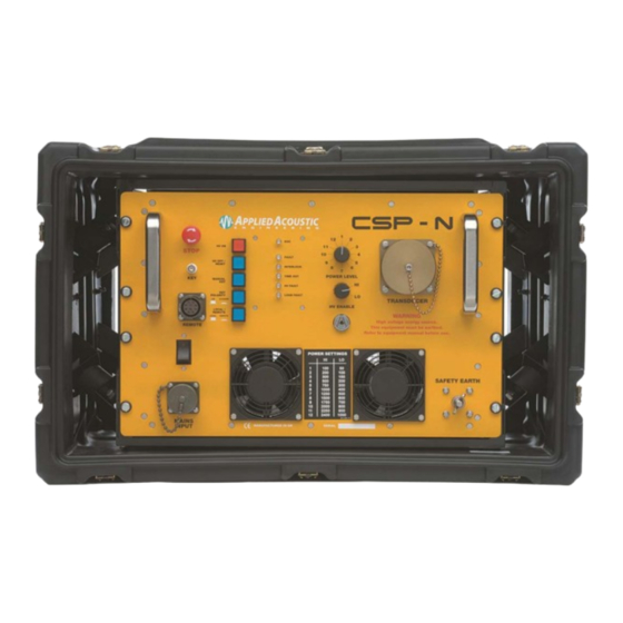
CSPN Capacitor Charging Unit Operation Manual CSP-CSPN-8000/1 __________________________________________________________________________________________________________ 1.2. Introduction The CSP-N is an evolution of the CSP-D range of seismic power supplies. The CSP-N has a high voltage charger rated at 2000 joules per second, and can supply up to 1200 or 2400 joules of energy per shot into the seismic sound source for example Dura-Spark. -
Page 9: Installation
CSPN Capacitor Charging Unit Operation Manual CSP-CSPN-8000/1 __________________________________________________________________________________________________________ 1.3. Installation Siting the CSP-N The CSP-N deliver high energy, high voltage pulses, yet still emit minimal electrical emissions, and so can carry the CE mark. The CE marking ensure that the CSP-N can be sited next to sensitive electronic equipment which carry their own CE marking (for susceptibility to emissions) and will be unlikely to cause them interference. -
Page 10: Earthing
CSPN Capacitor Charging Unit Operation Manual CSP-CSPN-8000/1 __________________________________________________________________________________________________________ Earthing The CSP-N MUST be earthed. The M8 earth bolt on the front panel should be connected to the vessel earth by a heavy gauge wire or cable. On larger ships, earth is usually a steel bulkhead, but for smaller fibre glass / wooden vessels a sea earth is necessary. -
Page 11: Installation
CSPN Capacitor Charging Unit Operation Manual CSP-CSPN-8000/1 __________________________________________________________________________________________________________ Installation The CSP-N Unit will normally be supplied from the factory in a ‘Hardigg’ transit case. As is the case with all electronic equipment, care should be exercised in handling. For maximum airflow in high ambient temperatures it is recommended that the anti-vibration housing rear panel be removed. -
Page 12: Line Voltage Connection
CSPN Capacitor Charging Unit Operation Manual CSP-CSPN-8000/1 __________________________________________________________________________________________________________ Output Cable Connection Continued In the situation of the power cable / sound source being caught on an object, the HV cable is pulled from the HV Junction Box, rather than the CSP-N unit being pulled onto the floor. The junction box is usually supplied with a 1.5 metre lead, terminated in our HV connector. -
Page 13: Ac Power Requirements
CSPN Capacitor Charging Unit Operation Manual CSP-CSPN-8000/1 __________________________________________________________________________________________________________ AC Power Requirements Voltage ratings are quoted elsewhere in this manual. Typical Currents At 1500J at 1 pps (AVIP out of circuit); Non PFC charger, the following currents apply:- Voltage Peak Current Average Current 240 VAC 50 Hz... -
Page 14: Local Remote
CSPN Capacitor Charging Unit Operation Manual CSP-CSPN-8000/1 __________________________________________________________________________________________________________ Local / Remote The LOCAL / REMOTE switch allows connection of remote box for operation from the laboratory or instrument room. Using the remote box is achieved by turning the LOCAL / REMOTE switch to remote. -
Page 15: Operation
CSPN Capacitor Charging Unit Operation Manual CSP-CSPN-8000/1 __________________________________________________________________________________________________________ 1.4. Operation Operation of the CSP-N is similar to previous versions of the CSP. Installation check-list:- a) The sound source (boomer plate or sparker) has been connected and that it is in the water. b) A key pulse is connected –... -
Page 16: Energy Settings
CSPN Capacitor Charging Unit Operation Manual CSP-CSPN-8000/1 __________________________________________________________________________________________________________ Energy Settings CSP-N 1200 OUTPUT POWER SWITCH POSITION 1000 1100 1200 CSP-N 2400 OUTPUT POWER SWITCH POSITION 1000 1250 1500 1750 2000 2250 2400 1000 Items marked in red are not suitable for a single boomer. ... -
Page 17: Operation Of The Csp-Nwith A Boomer Sound Source
CSPN Capacitor Charging Unit Operation Manual CSP-CSPN-8000/1 __________________________________________________________________________________________________________ Operation of the CSP-N with a Boomer Sound Source A boomer plate as a sound source produces a single pulse and the amplitude and duration of this pulse is controlled by the energy going into it. The energy is derived from the voltage and the quantity of energy stored in the CSP unit. -
Page 18: Operation Of The Csp-Nwith A Sparker Sound Source
CSPN Capacitor Charging Unit Operation Manual CSP-CSPN-8000/1 __________________________________________________________________________________________________________ Operation of the CSP-N with a Sparker Sound Source The CSP-N is designed for use with the Dura-Spark Sparker. The CSP-N is not compatible with the Squid Sparker range of sparker sound sources due to the polarity of the power supply. The polarity of the CSP-N reduces tip wear to a minimum ensuring a stable repeatable sound source. -
Page 19: Operator Controls And Indicators
CSPN Capacitor Charging Unit Operation Manual CSP-CSPN-8000/1 __________________________________________________________________________________________________________ 1.5. Operator Controls and Indicators MAINS POWER Switch Double pole switch that also acts as an over current circuit breaker. It is situated by the mains input connector. The switch has standard O I positions. EMERGENCY STOP switch In the event of an emergency the unit can be shut down. -
Page 20: Indicators
CSPN Capacitor Charging Unit Operation Manual CSP-CSPN-8000/1 __________________________________________________________________________________________________________ 1.5.1 Indicators EOC (End Of Charge) Indicator LED illuminated when the storage capacitors have reached their potential voltage (~2.5 to 4 kV). In this way the operator can see if the unit is being run faster than the charger can cope with. If the operator notices loss of data on the recording system, it may mean the CSP-N is being fired too quickly, not allowing the capacitors to charge to their full potential. -
Page 21: Connectors
CSPN Capacitor Charging Unit Operation Manual CSP-CSPN-8000/1 __________________________________________________________________________________________________________ 1.5.2. Connectors Mains Input 200 – 250 VAC mains input. Connection details are supplied elsewhere in this manual. Remote Allows operator to remotely control CSP-N. HV Output 4 pin proprietary connector. Using our HV2 plug, the large connector pins are proof tested to 6000 volts and can operate with current pulses up to 8000 amps. -
Page 22: Product Recycling / Disposal
Within the EU all electronic components and batteries must be taken for separate collection at the end of their working life under EU WEEE directives. Applied Acoustics as a manufacturer within the EU will responsibly dispose of any returned end of life Applied Acoustics components / batteries through a registered WEEE scheme. -
Page 23: Specifications
CSPN Capacitor Charging Unit Operation Manual CSP-CSPN-8000/1 __________________________________________________________________________________________________________ 1.8. Specifications CSP-N Series Capacitor Discharge Power Supplies Models Available CSP-N 1200 : 2000J/s at up to 1200J/shot. Peak charge rate. CSP-N 2400 : 2000J/s at up to 2400J/shot. Peak charge rate. -
Page 24: Safety Features
CSPN Capacitor Charging Unit Operation Manual CSP-CSPN-8000/1 __________________________________________________________________________________________________________ Safety Features Should any fault develop, the high voltage PSU (Charger) and all capacitors (which have bleed resistors) are individually dumped to ground, until the system is reset. A double layer of safety cut- outs ensure that partial failure results in system shutdown. -
Page 25: Section 2 - Troubleshooting
CSPN Capacitor Charging Unit Operation Manual CSP-CSPN-8000/1 __________________________________________________________________________________________________________ Section 2 - TROUBLESHOOTING 2.1. Introduction The CSP-N has been designed so that the operator does not need to remove the top cover for any operational adjustments. The top cover should only be removed by factory trained personnel, and the following points should be noted. -
Page 26: Circuits And Descriptions
CSPN Capacitor Charging Unit Operation Manual CSP-CSPN-8000/1 __________________________________________________________________________________________________________ 2.2. Circuits and Descriptions The following pages give brief circuit descriptions for major items inside the CSP Unit itself. The descriptions should be read in conjunction with the diagrams (Schematics). The CSP-N is part of the CSP range of seismic power supplies and shares common chassis components as the CSP-D, -P, -S therefore there are references made to these parts and drawings. -
Page 27: High Voltage Section
CSPN Capacitor Charging Unit Operation Manual CSP-CSPN-8000/1 __________________________________________________________________________________________________________ High Voltage Section The right side of the unit contains the high voltage parts. Each capacitor is switched in and out of circuit by 12 kV rated, spring relays. The relays use a rotating moving contact which is silver plated. -
Page 28: Ac Section
CSPN Capacitor Charging Unit Operation Manual CSP-CSPN-8000/1 __________________________________________________________________________________________________________ AC Section The AC Section is to the left of the charger. Access to it can be gained by firstly removing the capacitor support clamp and then taking out the screws which hold the LH panel in place. Note that you will also have to disconnect or remove the interlock switch. -
Page 29: Control Board
CSPN Capacitor Charging Unit Operation Manual CSP-CSPN-8000/1 __________________________________________________________________________________________________________ Control Board Drawing No: CSP-1000-5000 - Section 3 Key Board Drawing No: CSP-CSPD-5109 - Section 3 The power supply can be triggered using any of the following:- 1. Key in is via the BNC connector on the front panel. The key source is opto-isolated, and this can be either a pulse (3-24VDC) or a contact closure, selectable using the key polarity switch on the front panel. -
Page 30: Fault Latches / Hv On Circuit
CSPN Capacitor Charging Unit Operation Manual CSP-CSPN-8000/1 __________________________________________________________________________________________________________ Fault Latches / HV on Circuit Drawing No: CSP1000-5000 - Section 3. A reset / fault condition can occur due to any of the following:- 1. High voltage connector to transducer not being connected while power supply is switched ON. 2. -
Page 31: High Voltage On Circuit
CSPN Capacitor Charging Unit Operation Manual CSP-CSPN-8000/1 __________________________________________________________________________________________________________ High Voltage On Circuit The high voltage can be activated from the power supply front panel, or remotely from the instrument room using the remote box and cable. Both switches are controlled using the Remote / Local (R/L) switch on the front panel. -
Page 32: Interlocks / Relay Board
CSPN Capacitor Charging Unit Operation Manual CSP-CSPN-8000/1 __________________________________________________________________________________________________________ Interlocks / Relay Board Drawing No: CSP1000-5002 - Section 3 The mains input for the high voltage charger is routed via a contactor controlled from the relay board located under the left side panel. A small mains transformer and rectifier provide 12VDC to operate the contactor relay. -
Page 33: Repair And Fault Finding On Csp Power Supplies
CSPN Capacitor Charging Unit Operation Manual CSP-CSPN-8000/1 __________________________________________________________________________________________________________ 2.3. Repair and Fault Finding on CSP Power Supplies It is not recommended that any internal repairs are undertaken to any CSPD by anyone other than a suitably qualified engineer. AAE can take no responsibility for loss or injury caused by repairs that have not been performed either within our own Laboratories or by our own registered service agents. -
Page 34: Csp-N Basic Fault Diagnosis
CSPN Capacitor Charging Unit Operation Manual CSP-CSPN-8000/1 __________________________________________________________________________________________________________ 2.4. CSP-N Basic Fault Diagnosis Unit Dead First check the integrity of the mains supply fuse and the mains supply itself, if the fuse itself has blown try the following components: ... -
Page 35: __________________________________________________________________________________________________________
CSPN Capacitor Charging Unit Operation Manual CSP-CSPN-8000/1 __________________________________________________________________________________________________________ Unit Resets as Normal, HV Will Not Select Check position of Remote/Local switch. Also: Replace Control Board Replace Front Panel Board Replace Front Panel Power Selection Switch HV Relays Operate but no EOC Lamp Suspect HV Charger or HV BNC charger cable. -
Page 36: Troubleshooting Guide
CSPN Capacitor Charging Unit Operation Manual CSP-CSPN-8000/1 __________________________________________________________________________________________________________ 2.5. Troubleshooting Guide POWER SELECT SWITCH SHOULD BE LEFT ON 100 JOULES This section is to be carried out by trained personnel only and undertaken in a safe environment. A transducer or dummy load should be connected to the unit, prior to these tests. -
Page 37: __________________________________________________________________________________________________________
CSPN Capacitor Charging Unit Operation Manual CSP-CSPN-8000/1 __________________________________________________________________________________________________________ Before carrying out the following checks, remove AC power to High Voltage Charger by disconnecting the yellow crimp connectors on the large relay located below and to the left side of the Control Board. This will disable the 4kV supply. POWER SELECT SWITCH SHOULD BE LEFT ON 100 JOULES This section is to be carried out by trained personnel only and undertaken in a safe environment. -
Page 38: __________________________________________________________________________________________________________
CSPN Capacitor Charging Unit Operation Manual CSP-CSPN-8000/1 __________________________________________________________________________________________________________ Possible Fault Problem Test Action Condition When HV ON button is pressed HV LED comes on (after approximately Fuse F2 blown. Check with ohm meter. Replace. 3 seconds) but HV relay(s) do not operate. -
Page 39: Maintenance Check List
CSPN Capacitor Charging Unit Operation Manual CSP-CSPN-8000/1 __________________________________________________________________________________________________________ 2.6. Maintenance Check List This checklist is intended as a recommended checklist to ensure safe and correct operation of the CSP Power Supply. It is intended for trained engineers only. Please refer to system manuals, CSP documentation or contact Applied Acoustic Engineering if you require assistance. -
Page 40: Section 3 - Circuit And Block Diagrams
CSPN Capacitor Charging Unit Operation Manual CSP-CSPN-8000/1 __________________________________________________________________________________________________________ SECTION 3 – CIRCUIT AND BLOCK DIAGRAMS 3.1. Introduction Section 3 contains schematics only. For circuit descriptions refer to Section 2. Circuit and Block Diagrams Index Drawing No Description Page CSP-1000-5000 CSP Control Brd Schematic 1 of 2 CSP-1000-5000... -
Page 41: __________________________________________________________________________________________________________
CSPN Capacitor Charging Unit Operation Manual CSP-CSPN-8000/1 __________________________________________________________________________________________________________ __________________________________________________________________________________________________________ Page 41 of 63... -
Page 42: __________________________________________________________________________________________________________
CSPN Capacitor Charging Unit Operation Manual CSP-CSPN-8000/1 __________________________________________________________________________________________________________ __________________________________________________________________________________________________________ Page 42 of 63... -
Page 43: __________________________________________________________________________________________________________
CSPN Capacitor Charging Unit Operation Manual CSP-CSPN-8000/1 __________________________________________________________________________________________________________ __________________________________________________________________________________________________________ Page 43 of 63... -
Page 44: __________________________________________________________________________________________________________
CSPN Capacitor Charging Unit Operation Manual CSP-CSPN-8000/1 __________________________________________________________________________________________________________ __________________________________________________________________________________________________________ Page 44 of 63... -
Page 45: __________________________________________________________________________________________________________
CSPN Capacitor Charging Unit Operation Manual CSP-CSPN-8000/1 __________________________________________________________________________________________________________ __________________________________________________________________________________________________________ Page 45 of 63... -
Page 46: __________________________________________________________________________________________________________
CSPN Capacitor Charging Unit Operation Manual CSP-CSPN-8000/1 __________________________________________________________________________________________________________ __________________________________________________________________________________________________________ Page 46 of 63... -
Page 47: __________________________________________________________________________________________________________
CSPN Capacitor Charging Unit Operation Manual CSP-CSPN-8000/1 __________________________________________________________________________________________________________ __________________________________________________________________________________________________________ Page 47 of 63... -
Page 48: __________________________________________________________________________________________________________
CSPN Capacitor Charging Unit Operation Manual CSP-CSPN-8000/1 __________________________________________________________________________________________________________ __________________________________________________________________________________________________________ Page 48 of 63... -
Page 49: __________________________________________________________________________________________________________
CSPN Capacitor Charging Unit Operation Manual CSP-CSPN-8000/1 __________________________________________________________________________________________________________ __________________________________________________________________________________________________________ Page 49 of 63... -
Page 50: __________________________________________________________________________________________________________
CSPN Capacitor Charging Unit Operation Manual CSP-CSPN-8000/1 __________________________________________________________________________________________________________ __________________________________________________________________________________________________________ Page 50 of 63... -
Page 51: __________________________________________________________________________________________________________
CSPN Capacitor Charging Unit Operation Manual CSP-CSPN-8000/1 __________________________________________________________________________________________________________ __________________________________________________________________________________________________________ Page 51 of 63... -
Page 52: __________________________________________________________________________________________________________
CSPN Capacitor Charging Unit Operation Manual CSP-CSPN-8000/1 __________________________________________________________________________________________________________ __________________________________________________________________________________________________________ Page 52 of 63... -
Page 53: __________________________________________________________________________________________________________
CSPN Capacitor Charging Unit Operation Manual CSP-CSPN-8000/1 __________________________________________________________________________________________________________ __________________________________________________________________________________________________________ Page 53 of 63... -
Page 54: __________________________________________________________________________________________________________
CSPN Capacitor Charging Unit Operation Manual CSP-CSPN-8000/1 __________________________________________________________________________________________________________ __________________________________________________________________________________________________________ Page 54 of 63... -
Page 55: __________________________________________________________________________________________________________
CSPN Capacitor Charging Unit Operation Manual CSP-CSPN-8000/1 __________________________________________________________________________________________________________ __________________________________________________________________________________________________________ Page 55 of 63... -
Page 56: __________________________________________________________________________________________________________
CSPN Capacitor Charging Unit Operation Manual CSP-CSPN-8000/1 __________________________________________________________________________________________________________ __________________________________________________________________________________________________________ Page 56 of 63... -
Page 57: __________________________________________________________________________________________________________
CSPN Capacitor Charging Unit Operation Manual CSP-CSPN-8000/1 __________________________________________________________________________________________________________ __________________________________________________________________________________________________________ Page 57 of 63... -
Page 58: __________________________________________________________________________________________________________
CSPN Capacitor Charging Unit Operation Manual CSP-CSPN-8000/1 __________________________________________________________________________________________________________ __________________________________________________________________________________________________________ Page 58 of 63... -
Page 59: __________________________________________________________________________________________________________
CSPN Capacitor Charging Unit Operation Manual CSP-CSPN-8000/1 __________________________________________________________________________________________________________ __________________________________________________________________________________________________________ Page 59 of 63... -
Page 60: Section 4 - System Interconnection
CSPN Capacitor Charging Unit Operation Manual CSP-CSPN-8000/1 __________________________________________________________________________________________________________ Section 4 – System Interconnection HVJ3001 HV Junction Box The CSP-N is supplied with the HV Junction Box HVJ3001, for use with the following sound sources and HV Cables. Seismic Power Supply HV Cable Sound Source CSP-N... -
Page 61: Double Array Arrangement
CSPN Capacitor Charging Unit Operation Manual CSP-CSPN-8000/1 __________________________________________________________________________________________________________ 4.2. Double Array Arrangement 240 Tips DuraSpark 400 // 160 Tips DuraSpark 240 // 2 Boomer Plate S-Boom 4.3. Single Array Arrangement 80 Tips DuraSpark 400 and 240 // Single Boomer Plate S-Boom __________________________________________________________________________________________________________ Page 61 of 63... -
Page 62: __________________________________________________________________________________________________________
CSPN Capacitor Charging Unit Operation Manual CSP-CSPN-8000/1 __________________________________________________________________________________________________________ 4.4. HVJ3001 Interconnections 4.5. HVJ3001 Junction Box Interlock Wiring __________________________________________________________________________________________________________ Page 62 of 63... - Page 63 ...
Need help?
Do you have a question about the CSP-N Series and is the answer not in the manual?
Questions and answers