Table of Contents
Advertisement
Quick Links
Advertisement
Table of Contents

Related Manuals for APPLIED ACOUSTICS CSP-SNv 1250


Summary of Contents for APPLIED ACOUSTICS CSP-SNv 1250
- Page 1 CSP-SNv 1250 / 2400 Capacitor Charging Unit Operation Manual...
-
Page 2: Revision History
CSP-SNv Capacitor Charging Unit Operation CSP-CSPSNV-8000/3 Manual _______________________________________________________________________________________________ Revision History Change Issue Reason for change Date 2542 CSP-SNv 2400 power settings updated. 29/07/21 2504 Appendix C Q.C. Log Format updated. 19/04/21 Sections 1.5 Settings, 1.5 Download Log & Specifications 2488 17/02/21 Production Issue. -
Page 3: Table Of Contents
CSP-SNv Capacitor Charging Unit Operation CSP-CSPSNV-8000/3 Manual _______________________________________________________________________________________________ Table of Contents REVISION HISTORY ............................2 SECTION 1 - OPERATIONAL ..........................7 1.1. ENVIRONMENTAL CONSIDERATIONS ....................... 7 1.2. INTRODUCTION ............................8 1.3. INSTALLATION ............................10 CSP-SN ITING THE ............................10 1.4 CONNECTIONS AND INDICATORS ......................12 AFETY ARTH .............................. - Page 4 CSP-SNv Capacitor Charging Unit Operation CSP-CSPSNV-8000/3 Manual _______________________________________________________________________________________________ ..................................23 & D ............................. 23 ..................................23 OWNLOAD ............................. 24 NERGY ETTINGS ............................25 NFORMATION ..............................26 PERATION ..............................27 1.6. OPERATION: ENABLING HIGH VOLTAGE STARTING OPERATIONS ............. 30 OWER ..............................30 ETTINGS ................................
- Page 5 APPENDIX C – CSP-DV / CSP-NV / CSP-SNV LOG - MCU F/W 1.13 ............52 APPENDIX D – GENERAL DIMENSIONS ......................55 Thank you for choosing applied acoustics ltd as one of your equipment suppliers. We hope you experience many years of reliable operational use from our products.
- Page 6 CSP-SNv Capacitor Charging Unit Operation CSP-CSPSNV-8000/3 Manual _______________________________________________________________________________________________ WARNING HIS EQUIPMENT CONTAINS LETHAL VOLTAGES AND MUST BE EARTHED AT ALL TIMES NSURE ADEQUATE SAFETY PROCEDURES ARE EMPLOYED Information in this manual is copyright 1993 – 2016, Applied Acoustic Engineering Ltd. This manual is loaned without other consideration than the agreement and condition that it is not to be reproduced, copied or otherwise disposed of directly, and is not to be used in whole or in part to assist in or to furnish any information for the making of...
-
Page 7: Section 1 - Operational
CSP-SNv Capacitor Charging Unit Operation CSP-CSPSNV-8000/3 Manual _______________________________________________________________________________________________ Section 1 - OPERATIONAL 1.1. Environmental Considerations Seismic Sound Sources and Marine Life Although not proven, there is concern in some quarters that marine mammals may be harmed or their behaviour changed by seismic activity. The sound pulses from sparkers and boomers is much lower in amplitude and higher in frequency (so it will travel less far) than air guns. -
Page 8: Introduction
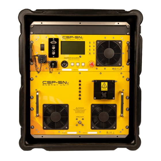
CSP-SNv Capacitor Charging Unit Operation CSP-CSPSNV-8000/3 Manual _______________________________________________________________________________________________ 1.2. Introduction The CSP-SNv is an evolution of the CSP-S range of seismic power supplies. The CSP-SNv has a high voltage charger rated at 4000 joules per second (peak), and can supply up to 1250 or 2400 joules of energy per shot into the seismic sound source, for example Dura-Spark. - Page 9 CSP-SNv Capacitor Charging Unit Operation CSP-CSPSNV-8000/3 Manual _______________________________________________________________________________________________ The CSP-SNv is a 2-module system comprised of: Control Unit System interface, control & monitoring • HV Charger • System mains input • Energy Unit Relay-switchable HV capacitor bank • HV energy switch •...
-
Page 10: Installation
CSP-SNv Capacitor Charging Unit Operation CSP-CSPSNV-8000/3 Manual _______________________________________________________________________________________________ 1.3. Installation Siting the CSP-SNv The CSP-SNv delivers high energy, high voltage pulses, yet still emits minimal electrical emissions, and so can carry the CE mark. The CE marking ensure that the CSP-SNv can be sited next to sensitive electronic equipment which carry their own CE marking (for susceptibility to emissions) and will be unlikely to cause them interference. - Page 11 CSP-SNv Capacitor Charging Unit Operation CSP-CSPSNV-8000/3 Manual _______________________________________________________________________________________________ EARTHING - FURTHER REMINDER THIS UNIT MUST BE EARTHED / GROUNDED BEFORE ANY POWER IS APPLIED. FAILURE TO DO SO MAY REPRESENT A SEVERE HAZARD TO BOTH EQUIPMENT AND PERSONNEL. The front of the CSP-SNv must be grounded to the ship’s ground system. This is achieved by attaching a short length of thick wire or earth braid from the CSP-SNv front panel earth stud, to an appropriate earthing point on the vessel.
-
Page 12: Connections And Indicators
CSP-SNv Capacitor Charging Unit Operation CSP-CSPSNV-8000/3 Manual _______________________________________________________________________________________________ 1.4 Connections and Indicators Safety Earth The CSP-SNv MUST be earthed. The M8 earth bolt on the front panel should be connected to the vessel earth by a heavy gauge wire or cable. Typically 25mm² or greater. -
Page 13: Transducer: Hv Output
CSP-SNv Capacitor Charging Unit Operation CSP-CSPSNV-8000/3 Manual _______________________________________________________________________________________________ Transducer: HV Output HV GND HV NEGATIVE M8 THREADED M8 THREADED INTERLOCK The 2-pin proprietary high voltage and current terminal connector, is designed to be provide a safe electromechanical connection from the CSP Power supply to the HV Junction Box. -
Page 14: Mains Input: Line Voltage Connection
CSP-SNv Capacitor Charging Unit Operation CSP-CSPSNV-8000/3 Manual _______________________________________________________________________________________________ Mains Input: Line Voltage Connection Mains input is connected by the 3-Pin Amphenol on the left of the front panel. Nominal input voltage is 230VAC 45-65 Hz. The wiring to this connector is as follows:- Ground / Earth Neutral Live... -
Page 15: Com Serial Connector
CSP-SNv Capacitor Charging Unit Operation CSP-CSPSNV-8000/3 Manual _______________________________________________________________________________________________ COM Serial Connector 2 Receive Data (RXD) 3 Transmit Data (TXD) 5 GND Allows operator to update control firmware. Refer Appendix A. REMOTE Socket Allows operator to remotely control CSP-SNv. KEY IN Input BNC The Key In Input is connected via a BNC connector. -
Page 16: Manual Key Switch
CSP-SNv Capacitor Charging Unit Operation CSP-CSPSNV-8000/3 Manual _______________________________________________________________________________________________ MANUAL KEY Switch Triggers the CSP unit when Manual Key mode is selected. MANUAL KEY switch indicator will flash briefly on key press. Manual Key Mode must be selected to active manual fire mode. MAINS POWER Switch Double-pole switch that also acts as an over-current circuit breaker. -
Page 17: Key Indicator
CSP-SNv Capacitor Charging Unit Operation CSP-CSPSNV-8000/3 Manual _______________________________________________________________________________________________ KEY Indicator Synchronised to Key Out. HV Indicator Indicates HV is enabled on system Local / Remote Indicator LOCAL Operation indicated by LED ON. REMOTE Operation indicated by LED OFF. FAULT Indicator It will illuminate during internal fault modes, see LCD display for fault identification. -
Page 18: Rear Panel Fuses
CSP-SNv Capacitor Charging Unit Operation CSP-CSPSNV-8000/3 Manual _______________________________________________________________________________________________ Rear Panel Fuses The rear panel contains 3 fuse holders, and these are the only things we recommend the operator checks if he has not received factory training. The fuses are rated as follows:- 3A Antisurge 1¼"... -
Page 19: Operation: System Configuration
1.5 Operation: System Configuration On turn on, splash screen will detail CSP model and a safety warning: Applied Acoustic Eng. Ltd. CSP-SNv 1250 THIS UNIT CONTAINS LETHAL VOLTAGES AND MUST BE EARTHED AT ALL TIMES. ENSURE ADEQUATE SAFETY PROCEDURES ARE EMPLOYED FOR OPERATION OF THIS UNIT. -
Page 20: Settings
CSP-SNv Capacitor Charging Unit Operation CSP-CSPSNV-8000/3 Manual _______________________________________________________________________________________________ Settings SETTINGS Power: Refer section Energy Settings Level: High Key: Int (Internal) Ext (External) Manual (Key Press) Key In Polarity: Pos (Positive) Neg (Negative) Fire Delay: Fire Delay Time: 5uS to 500uS Key Out Polarity: Pos (Positive) Neg (Negative) -
Page 21: Fire Delay & Fire Delay Time Settings
CSP-SNv Capacitor Charging Unit Operation CSP-CSPSNV-8000/3 Manual _______________________________________________________________________________________________ Fire Delay & Fire Delay Time Settings There is a fixed 1mS delay between a key and the CSP firing (discharge of the CSP). With Fire Delay setting selected ‘On’, this delay is extended by the Fire Delay Time setting. -
Page 22: Flip-Flop Setting
CSP-SNv Capacitor Charging Unit Operation CSP-CSPSNV-8000/3 Manual _______________________________________________________________________________________________ Flip-Flop Setting With flip-flop setting selected ‘On’, the CSP is the master in master-slave operation as follows: At selected rate (internal, external or manual) the master will alternately fire or output a key pulse on KEY OUT BNC to key the slave. -
Page 23: Default Settings
CSP-SNv Capacitor Charging Unit Operation CSP-CSPSNV-8000/3 Manual _______________________________________________________________________________________________ Default Settings Default Settings Press OK for default settings OK to select, to exit Press to exit Press OK for default system settings. Set Time & Date Set Time & Date Set Time: 12:34:56 Set Date 01-JAN-2016... -
Page 24: Download Log
CSP-SNv Capacitor Charging Unit Operation CSP-CSPSNV-8000/3 Manual _______________________________________________________________________________________________ Download Log In operation mode, enabling HV ON begins an operational logging procedure. The log contains all CSP settings and operational status of up to the last 2042 keys received until HV OFF due to user intervention, fault or power supply interruption. The log is stored in non-volatile memory for retrieval using the COM serial connector by the user. -
Page 25: Energy Settings
1200 2000 2250 2400 CSP-SNv 1250 All power levels are suitable for the 3-Boom Catamaran. • Do not exceed the rated power levels of the connected sound source. The CSP-SNv is capable of delivering 4000J per second to a sound source - over driving a sound source will result in damage to equipment and present hazards to personnel. -
Page 26: Information
CSP-SNv Capacitor Charging Unit Operation CSP-CSPSNV-8000/3 Manual _______________________________________________________________________________________________ Information System information details model and serial number, plus current firmware revisions and operational time in days and hours. Information Model: CSP-SNv 1250 Serial Number: ************ MCU Firmware: **.** CPLD Firmware: **.** Operational: 000D 00H... -
Page 27: Operation
CSP-SNv Capacitor Charging Unit Operation CSP-CSPSNV-8000/3 Manual _______________________________________________________________________________________________ Operation Interlock Settings Fault: Power: 1250J Vkey: 3950v Level: High PSU: Key: Load: F/D: CSP: Rate: 1500ms AVIP: F/F: L/R: Local Tca: 29°C Tco: 16°C Teo: 30°C The operation mode displays system settings together with operational feedback of system status. - Page 28 CSP-SNv Capacitor Charging Unit Operation CSP-CSPSNV-8000/3 Manual _______________________________________________________________________________________________ “CSP” indicates status of the CSP power supply. CSP Status Description Fault Internal fault, e.g. Keyboard, Control Logic. Temp Temperature limit 0 to 45°C Time Key In Time Out, external or manual key not detected Mains Low VAC Mains Supply detected, limit 180VAC Remote Unit not detected.
- Page 29 CSP-SNv Capacitor Charging Unit Operation CSP-CSPSNV-8000/3 Manual _______________________________________________________________________________________________ Temperature Description Control Unit ambient temperature Control Unit outlet temperature Tout Energy Unit outlet temperature EOC Histogram The histogram displays the status of the end of charge voltage history of the last 20 shots, this allows the operator to monitor the system operation at a glance with instant feedback of the overall system performance.
-
Page 30: Operation: Enabling High Voltage Starting Operations
The power can be applied using the ON / OFF switch and circuit breaker. The front panel fans will run, and the HV OFF / RESET button will illuminate. Applied Acoustic Eng. Ltd. CSP-SNv 1250 THIS UNIT CONTAINS LETHAL VOLTAGES AND MUST BE EARTHED AT ALL TIMES. -
Page 31: Settings
CSP-SNv Capacitor Charging Unit Operation CSP-CSPSNV-8000/3 Manual _______________________________________________________________________________________________ Settings Main Menu Operation Settings Information 12:34:56 OK to select 15-MAR-2019 From main menu, use to navigate to Settings menu option. Press OK to select. Settings Power: 250J Level: High Key: Key In Polarity: Fire Delay: OK to select, to exit... - Page 32 CSP-SNv Capacitor Charging Unit Operation CSP-CSPSNV-8000/3 Manual _______________________________________________________________________________________________ Settings Internal Rate: 1000ms Key In Timeout: AVIP: Flip-Flop: QC Log Output: OK to select, to exit Select Internal Rate and AVIP settings. Key In Timeout can be set in the range of 10 to 120 seconds. to navigate settings.
-
Page 33: Operation
CSP-SNv Capacitor Charging Unit Operation CSP-CSPSNV-8000/3 Manual _______________________________________________________________________________________________ Operation Interlock Settings Fault: Power: 250J Vkey: Level: High PSU: Key: Load: F/D: CSP: Rate: 1500ms AVIP: F/F: L/R: Local Tca: 29°C Tco: 16°C Teo: 30°C HV OFF / RESET switch indicator will be ON, indicating High Voltage is OFF. All other indicators should be OFF Any Interlocks or fault modes will be displayed and indicated. -
Page 34: Operation: Enable High Voltage
CSP-SNv Capacitor Charging Unit Operation CSP-CSPSNV-8000/3 Manual _______________________________________________________________________________________________ Operation: Enable High Voltage To enable High Voltage press and hold the HV ON button for 3 seconds. Depending on settings, 1,2,3,4 or 5 relays will engage over a fixed 6 second period. High voltage will then enable, and the system will begin to cycle. -
Page 35: System Cycle Of Operation
CSP-SNv Capacitor Charging Unit Operation CSP-CSPSNV-8000/3 Manual _______________________________________________________________________________________________ System Cycle of Operation HV Capacitor(s) Key received. HV Capacitor(s) charged EOC ON Capacitors discharged, charged EOC ON System ready to EOC OFF. System ready to discharge upon arrival No fault lights ON, discharge upon arrival of Key system re-charges... -
Page 36: Local / Remote
CSP-SNv Capacitor Charging Unit Operation CSP-CSPSNV-8000/3 Manual _______________________________________________________________________________________________ Local / Remote Required: CSP-CSPDV-7060 Remote Unit CSP-CSPDV-4060 Remote Cable The Local / Remote setting allows the use of a Remote Unit for operation from a laboratory or instrument room. The Remote Unit mirrors the CSP HV ON and HV OFF switch indicators, plus EOC, KEY and general FAULT indicators, regardless of Local / Remote setting. -
Page 37: Operation: Enable High Voltage With Remote Unit
CSP-SNv Capacitor Charging Unit Operation CSP-CSPSNV-8000/3 Manual _______________________________________________________________________________________________ Operation: Enable High Voltage with Remote Unit • CSP Local / Remote setting must be set to Remote. CSP must be in OPERATION MODE. • HV must be off. • Fault modes must be reset. •... -
Page 38: Operation With A Boomer Sound Source
CSP-SNv Capacitor Charging Unit Operation CSP-CSPSNV-8000/3 Manual _______________________________________________________________________________________________ 1.7.1 Operation with a Boomer Sound Source A boomer plate as a sound source produces a single pulse and the amplitude and duration of this pulse is controlled by the energy going into it. The energy is derived from the voltage and the quantity of energy stored in the CSP unit. -
Page 39: Operation With A Sparker Sound Source
CSP-SNv Capacitor Charging Unit Operation CSP-CSPSNV-8000/3 Manual _______________________________________________________________________________________________ 1.7.2 Operation with a Sparker Sound Source The CSP-SNv is designed for use with the Dura-Spark Sparker. The CSP-SNv is not compatible with the Squid Sparker range of sparker sound sources due to the polarity of the power supply. -
Page 40: Product Recycling / Disposal
CSP-SNv Capacitor Charging Unit Operation CSP-CSPSNV-8000/3 Manual _______________________________________________________________________________________________ 1.8. Product Recycling / Disposal Within the UK, all electronic components and batteries must be taken for separate collection at the end of their working life under the Waste Electrical and Electronic Equipment (WEEE) Regulations 2013 and Waste Batteries and Accumulators Regulations 2009 respectively. -
Page 41: System Interconnection
CSP-SNv Capacitor Charging Unit Operation CSP-CSPSNV-8000/3 Manual _______________________________________________________________________________________________ 1.9 System Interconnection HVJ3004 HV Junction Box The CSP-SNv is supplied with the HV Junction Box HVJ3004, for use with the following sound sources and HV Cables. Seismic Power Supply HV Cable Sound Source CSP-SNv HVC 3000... -
Page 42: Double Array Arrangement
CSP-SNv Capacitor Charging Unit Operation CSP-CSPSNV-8000/3 Manual _______________________________________________________________________________________________ Double Array Arrangement 240 Tips DuraSpark 400 // 160 Tips DuraSpark 240 // 2 Boomer Plate S-Boom Single Array Arrangement 80 Tips DuraSpark 400 and 240 // Single Boomer Plate S-Boom __________________________________________________________________________________________________________ Page 42 of 56... -
Page 43: Hvj3004 Interconnections
CSP-SNv Capacitor Charging Unit Operation CSP-CSPSNV-8000/3 Manual _______________________________________________________________________________________________ HVJ3004 Interconnections __________________________________________________________________________________________________________ Page 43 of 56... -
Page 44: Hvj3001 Junction Box Interlock Wiring
CSP-SNv Capacitor Charging Unit Operation CSP-CSPSNV-8000/3 Manual _______________________________________________________________________________________________ HVJ3001 Junction Box Interlock Wiring __________________________________________________________________________________________________________ Page 44 of 56... - Page 45 CSP-SNv Capacitor Charging Unit Operation CSP-CSPSNV-8000/3 Manual _______________________________________________________________________________________________ __________________________________________________________________________________________________________ Page 45 of 56...
-
Page 46: Specifications
Physical Specification Size Transit Case 19” rack 11U high Weight CSP-SNv 1250, case and cover: 90kg CSP-SNv 2400, case and cover: 93kg Electrical Specification Mains Input 240Vac 45-65Hz @ 6.0kVA single phase. 3 pin connector Variable Input Power Circuitry (AVIP) ‘soft start’ control... -
Page 47: Safety Features
CSP-SNv Capacitor Charging Unit Operation CSP-CSPSNV-8000/3 Manual _______________________________________________________________________________________________ Safety Features Main microprocessor control circuits with fail-safe layer of logic circuitry • LCD display with system status information, configuration • Specially designed HV connector with interlock • High speed dump resistors for high voltage components •... - Page 48 CSP-SNv Capacitor Charging Unit Operation CSP-CSPSNV-8000/3 Manual _______________________________________________________________________________________________ Appendix A – CSP Firmware Upgrade Requirements PC with RS232 serial port & Hyperterminal • RS232 cable (not crossover type) • Procedure Ensure CSP is turned off. Connect RS232 cable between PC serial port & CSP front panel COM port. Configure Hyperterminal for: 115200 baud 8 data bits...
- Page 49 CSP-SNv Capacitor Charging Unit Operation CSP-CSPSNV-8000/3 Manual _______________________________________________________________________________________________ Press 1 on PC keyboard. Message “Waiting for file to be sent …” will be displayed. Select “Transfer”->”Send File” on Hyperterminal. Box “Send File” will open. Select Protocol “Ymodem”. Select “Browse” then navigate to and select .bin file to open.
- Page 50 CSP-SNv Capacitor Charging Unit Operation CSP-CSPSNV-8000/3 Manual _______________________________________________________________________________________________ Appendix B – Remote Unit Firmware Upgrade Requirements PC with RS232 serial port & Hyperterminal • RS232 cable (not crossover type) • CSP-CSPDV-4060 Remote Cable. • Procedure Ensure CSP is turned off. For safety, also engage CSP EMERGENCY STOP. If connected, disconnect Remote Unit from Remote Cable.
- Page 51 CSP-SNv Capacitor Charging Unit Operation CSP-CSPSNV-8000/3 Manual _______________________________________________________________________________________________ Hyperterminal should display the following: Press 1 on PC keyboard. Message “Waiting for file to be sent …” will be displayed. Select “Transfer”->”Send File” on Hyperterminal. Box “Send File” will open. Select Protocol “Ymodem”. Select “Browse” then navigate to and select .bin file to open.
- Page 52 CSP-SNv Capacitor Charging Unit Operation CSP-CSPSNV-8000/3 Manual _______________________________________________________________________________________________ Appendix C – CSP-Dv / CSP-Nv / CSP-SNv Log - MCU F/W 1.13 Log download after last CSP operation Settings Format: $SETTINGS,<MODEL>,<SERIAL NO>,<MCU F/W>,<CPLD F/W>,<POWER>,<LEVEL>, <KEY SOURCE>,<KEY IN POLARITY>,<KEY IN DELAY>,<KEY IN DELAY TIME>, <KEY OUT POLARITY>,<INTERNAL RATE>,<KEY IN TIMEOUT>,<AVIP>,<FLIP-FLOP>, <QC LOG OUTPUT>,<LOCAL/REMOTE>,<LCD CONTRAST>,<EOC LIMIT>,<CURRENT LIMIT>, <32-BIT HEX PEAK CURRENT SCALER>,<KEY IN OFFSET>,<CHARGE PROFILE>:...
- Page 53 CSP-SNv Capacitor Charging Unit Operation CSP-CSPSNV-8000/3 Manual _______________________________________________________________________________________________ QC Log Format output per shot QC Log is appended with EOC status: $LOG,<EOC STATUS>,<POWER>,<LEVEL>,<TIME>,<DATE>,<32-BIT HEX KEY NUMBER>, <KEY RATE>,<PRE-FIRE VOLTAGE>,<POST FIRE VOLTAGE>,<PEAK CURRENT>, <TAMBIENT>,<TINLET>,<TOUTLET>, <32-BIT HEX EVENT FLAGS>,<32-BIT HEX FAULT FLAGS>: Example QC Logs: $LOG,EOC=Y,01000J,LO,14:44:59,24-MAY-2018,00001786,0200ms,2504v,0022v,6446A, 25c,26c, 24c,00020080,00000000:...
- Page 54 CSP-SNv Capacitor Charging Unit Operation CSP-CSPSNV-8000/3 Manual _______________________________________________________________________________________________ Fault Flags Format is 32-bit hex long word. All fault flags are logged. Bit descriptions below: DESCRIPTION HV OFF LATCH INTERLOCK LATCH FAULT LATCH HV FAULT LATCH KEY IN TIMEOUT FAULT HV SHORT CIRCUIT FAULT HV OPEN CIRCUIT FAULT HV CHARGER SUMMARY FAULT HV CHARGER LOAD FAULT...
- Page 55 CSP-SNv Capacitor Charging Unit Operation CSP-CSPSNV-8000/3 Manual _______________________________________________________________________________________________ Appendix D – General Dimensions __________________________________________________________________________________________________________ Page 55 of 56...
Need help?
Do you have a question about the CSP-SNv 1250 and is the answer not in the manual?
Questions and answers