Table of Contents
Advertisement
Quick Links
Advertisement
Table of Contents

Related Manuals for Vacon FI9


Summary of Contents for Vacon FI9
- Page 1 – fi14...
- Page 2 All parameters are explained in the All in One Application Manual. Follow the commissioning instructions, see Chapter 8. The Vacon NX Inverter is now ready for use. Vacon Plc is not responsible for the use of the inverters against the instructions.
-
Page 3: Table Of Contents
CONTENTS VACON NXI USER’S MANUAL INDEX SAFETY EU DIRECTIVE RECEIPT OF DELIVERY TECHNICAL DATA INSTALLATION CABLING AND CONNECTIONS CONTROL KEYPAD COMMISSIONING FAULT TRACING... - Page 4 Congratulations for choosing Vacon NX Inverters! The User's Manual will provide you with the necessary information about the installation, commissioning and operation of Vacon NX Inverters. We recommend that you carefully study these instructions before powering up the inverter for the first time.
-
Page 5: Index
TECHNICAL DATA ......................15 Introduction..........................15 Power ratings..........................17 4.2.1 Vacon NXI_xxxx 5 – Supply voltage 465-800 Vdc, Motor voltage 380—500 Vac ....17 4.2.2 Vacon NXI_xxxx 6 – Supply voltage 640-1100 Vdc, Motor voltage 525—690 Vac...18 Technical information....................... 19 INSTALLATION ......................... 22 Mounting ........................... - Page 6 6 • vacon 6.1.1.8 Terminal sizes, NXI_xxxx 6 ..................46 6.1.2 Installation instructions ....................47 6.1.2.1 Vacon NXI frames ....................49 6.1.3 Cable installation and the UL standards ................51 6.1.4 Cable and motor insulation checks ................51 Control unit ..........................52 6.2.1 Control connections ......................53 6.2.1.1...
-
Page 7: Safety
THE ELECTRICAL INSTALLATION Warnings The components of the power unit of the inverter are live when the Vacon NX is connected to DC supply. Coming into contact with this voltage is extremely dangerous and may cause death or severe injury. The control unit is isolated from mains potential. - Page 8 8 • vacon SAFETY Earthing and earth fault protection The Vacon NX inverter must always be earthed with an earthing conductor connected to the earthing terminal. The earth fault protection inside the inverter only protects the inverter against earth faults in the motor or the motor cable.
-
Page 9: Eu Directive
(European Economic Area). It also guarantees that the product complies with applicable directives (for example, the EMC directive and other possible so-called new method directives). Vacon NX inverters carry the CE label as a proof of compliance with the Low Voltage Directive (LVD) and the Electro Magnetic Compatibility (EMC) directive. - Page 10 Safety: EN61800-5-1 (2003) EMC: Factory delivered Vacon NX inverter modules comply with the requirements of category 4 equipment according to EN 61800-3 (2004). It is ensured through internal measures and quality control that the product conforms at all times to the requirements of the current Directive and the relevant standards.
-
Page 11: Receipt Of Delivery
• 11 RECEIPT OF DELIVERY Vacon NX inverters have undergone scrupulous tests and quality checks at the factory before they are delivered to the customer. However, after unpacking the product, check that no signs of transportation damage is to be found on the product and that the delivery is complete (compare the... - Page 12 NXI_AAAA 5/6 Air cooling Alphanumeric control panel with fiber connection Standard features of EMC class T (EN 61800-3 for IT networks) FI9, FI10, FI12, Safety CE / UL FI13 and FI14 External charging required I/O modules A1 & A2 IP00 Table 3-1.
- Page 13 Regular maintenance is recommended to ensure trouble free operation and long lifetime of the drive. At least the following things should be included in the regular maintenance. 24-hour support: +358-(0)40-8371 150 • Email: vacon@vacon.com...
- Page 14 (General delivery terms NL92/Orgalime S92). The local distributor may grant a warranty time different from the above. This warranty time shall be specified in the distributor's sales and warranty terms. Vacon assumes no responsibility for any other warranties than that granted by Vacon itself.
-
Page 15: Technical Data
TECHNICAL DATA Introduction The figure below presents the block diagram of the Vacon NX inverter. The inverter mechanically consists of two units, the Power Unit and the Control Unit. The Power Unit contains an inverter bridge which consists of IGBT switches and produces a symmetrical, 3-phase PWM-modulated AC voltage to the motor. - Page 16 Instead of the control keypad, a PC can be used to control the inverter if connected through a similar cable (VACON RS232PC –1.5M). The basic control interface and the parameters (the Basic Application) are easy to use. If a more versatile interface or parameters are required, a more suitable application can be chosen from the "All in One+"...
- Page 17 • 17 Power ratings 4.2.1 Vacon NXI_xxxx 5 – Supply voltage 465-800 Vdc, Motor voltage 380—500 Vac High overload = Max current I ; 2 sec/20 sec, 150% overloadability; 1 min/10 min Following continuous operation at rated output current, 150 % rated...
- Page 18 18 • vacon technical data 4.2.2 Vacon NXI_xxxx 6 – Supply voltage 640-1100 Vdc, Motor voltage 525—690 Vac High overload = Max current I 2 sec/20 sec, 150% overloadability; 1 min/10 min Following continuous operation at rated output current, 150 % rated...
- Page 19 IEC 721-3-3, unit in operation, class 3S2 mechanical particles Altitude 100% load capacity (no derating) up to 1,000 m 1-% derating for each 100m above 1000.; max. 2000m (Continues on next page) 24-hour support: +358-(0)40-8371 150 • Email: vacon@vacon.com...
- Page 20 Storage and shipping: max 15 G, 11 ms (in package) Heat loss [kW] approx. P [kW] × 0,02 loss Cooling air required FI9 1150 m /h, FI10 1400 m FI12 2800 m /h, FI13 4200 m /h, FI14 2×4200 m Unit enclosure class...
- Page 21 0,91 1727 1770 0,92 2132 FI14 2150 0,92 2590 2700 0,92 3252 Table 4- 4 DC currents and dimensions of Vacon NXI, supply voltage 465 - 800Vdc Structure (output) Motor P.F. (input) 0,89 0,89 0,89 FI10 0,91 0,91 0,91 0,91...
-
Page 22: Installation
22 • vacon installation INSTALLATION Mounting The inverter can be mounted in a vertical position on the back plane of a cubicle. Enough space must be reserved around the inverter to ensure sufficient cooling, see Figure 5-7. Follow the minimum dimensions for installation, see Table 5-1 and Table 5-2. - Page 23 • 23 Figure 5-1. The dimensions of Vacon NXI FI9 24-hour support: +358-(0)40-8371 150 • Email: vacon@vacon.com...
- Page 24 24 • vacon installation Figure 5-2. Vacon NXI dimensions, FI10 Tel: +358-201-2121 • Fax: +358-201-212 205...
- Page 25 • 25 Figure 5-3. Vacon NXI dimensions, FI12 back view. 24-hour support: +358-(0)40-8371 150 • Email: vacon@vacon.com...
- Page 26 26 • vacon installation Figure 5-4. Vacon NXI dimensions, FI12 front view Tel: +358-201-2121 • Fax: +358-201-212 205...
- Page 27 • 27 Figure 5-5. Vacon NXI dimensions, FI13 back view. Note, FI14 is a douple FI13 24-hour support: +358-(0)40-8371 150 • Email: vacon@vacon.com...
- Page 28 28 • vacon installation Figure 5-6. Vacon NXI dimensions, FI13 front view. Note, FI14 is a douple FI13 Tel: +358-201-2121 • Fax: +358-201-212 205...
- Page 29 Table 5-1. Mounting space dimensions = free space above the inverter = distance between inverter and cabinet wall = distance between two inverters = free space underneath of the inverter Figure 5-7. Installation space. 24-hour support: +358-(0)40-8371 150 • Email: vacon@vacon.com...
- Page 30 Table 5-2 must be followed. For instance, there could be two screened gaps as presented in Figure 5-7 (Vacon's recommendation). This layout ensures a sufficient air flow to the module fans as well as cooling of the additional components.
-
Page 31: Cabling And Connections
• 31 Figure 5-8. Cabinet openings for cooling. 1. Cooling air inlets 2. Hot air exhaust 24-hour support: +358-(0)40-8371 150 • Email: vacon@vacon.com... - Page 32 32 • vacon cabling and connections STEERING AIR FLOW Cooling air must be taken in through the ventilation gaps on the door and blown out at the top of the enclosure. To steer the hot air from the power unit to the outlet at the top of the enclosure and...
- Page 33 Power unit The following wiring diagrams show the supply and motor connections. FI 9/10 CONTROL X10 H1...H7 X9 X15 U V W CHARGING CHARGING FEEDBACK RELAY Figure 6-1. FI9/10 basic wiring diagram without charging 24-hour support: +358-(0)40-8371 150 • Email: vacon@vacon.com...
- Page 34 34 • vacon cabling and connections EXTERNAL SUPPLY FI 9/10 CONTROL X10 H1...H7 X9 X15 CHARGING CHARGING FEEDBACK RELAY U V W Figure 6-2, FI9/10 basic wiring diagram with charging Tel: +358-201-2121 • Fax: +358-201-212 205...
- Page 35 • 35 FI10 MODULE 1 FI10 MODULE 2 CONTROL CHARGING CHARGING FEEDBACK RELAY U V W U V W Note! Min cable length 40m Figure 6-3, FI12 basic wiring diagram without charging 24-hour support: +358-(0)40-8371 150 • Email: vacon@vacon.com...
- Page 36 36 • vacon cabling and connections EXTERNAL SUPPLY FI10 MODULE 1 FI10 MODULE 2 CONTROL CHARGING CHARGING FEEDBACK RELAY U V W U V W Note! Min cable length 40m Figure 6-4, FI12 basic wiring diagram with charging Tel: +358-201-2121 • Fax: +358-201-212 205...
- Page 37 • 37 FI10 / MODULE U FI10 / MODULE V FI10 / MODULE W CONTROL CHARGING CHARGING FEEDBACK RELAY Figure 6-5, FI13 basic wiring diagram without charging 24-hour support: +358-(0)40-8371 150 • Email: vacon@vacon.com...
- Page 38 38 • vacon cabling and connections EXTERNAL SUPPLY FI10 / MODULE U FI10 / MODULE V FI10 / MODULE W CONTROL CHARGING CHARGING FEEDBACK RELAY Figure 6-6. FI13 basic wiring diagram with charging Tel: +358-201-2121 • Fax: +358-201-212 205...
- Page 39 FI10 / MODULE W FI10 / MODULE U FI10 / MODULE V FI10 / MODULE W CONTROL Note! CHARGING CHARGING Min cable FEEDBACK RELAY length 40m Figure 6-7. FI14 basic wiring diagram without charging 24-hour support: +358-(0)40-8371 150 • Email: vacon@vacon.com...
- Page 40 40 • vacon cabling and connections DC+ DC- DC+ DC- EXTERNAL EXTERNAL SUPPLY SUPPLY FI10 / MODULE U FI10 / MODULE V FI10 / MODULE W FI10 / MODULE U FI10 / MODULE V FI10 / MODULE W CONTROL CHARGING...
- Page 41 UL regulations is presented in Chapter 6.1.3 and aR fuse sizes in Tables 6-2 and 6-3. If the motor temperature protection of the drive (see Vacon All in One Application Manual) is used as an overload protection, the cable shall be chosen accordingly.
- Page 42 170M8547 3SHT 1250 2 × 6 NXI_2700 5 2700 170M8547 3SHT 1250 2 × 6 Table 6-2. Fuses used in Vacon NXI (465 - 800Vdc) 6.1.1.4 Fuses, NXI_xxxx 6 Fuse Fuse Bussman aR Fuse Type Frame No. of fuses fuse type...
- Page 43 Table valid for enclosure class IP20 cabinets Motor cables: EN 60204-1, IEC 60364-5-2/2001 - PVC insulation - 40 °C ambient temperature - 70 °C surface temperature Table 6-4. Cable sizes for Vacon NX_5 24-hour support: +358-(0)40-8371 150 • Email: vacon@vacon.com...
- Page 44 PE: M8 × 25 NXI_1030 5 1030 NXI_1150 5 1150 NXI_1300 5 FI13 1300 NXI_1450 5 1450 PE: M8 × 25 Table 6-5. Terminal sizes for Vacon NX_5 6.1.1.7 Inverter supply and motor cables, NXI_xxxx 6 Tel: +358-201-2121 • Fax: +358-201-212 205...
- Page 45 Table valid for enclosure class IP20 cabinets Motor cables: EN 60204-1, IEC 60364-5-2/2001 - PVC insulation - 40 °C ambient temperature - 70 °C surface temperature Table 6-6. Cable sizes for Vacon NX_6 24-hour support: +358-(0)40-8371 150 • Email: vacon@vacon.com...
- Page 46 PE: M8×25 NXI_0460 6 NXI_0502 6 NXI_0590 6 FI12 NXI_0650 6 NXI_0750 6 PE: M8×25 NXI_0820 6 NXI_0920 6 NXI_1030 6 FI13 1030 NXI_1180 6 1180 PE: M8×25 Table 6-7. Terminal sizes for Vacon NX_5 Tel: +358-201-2121 • Fax: +358-201-212 205...
- Page 47 D is tan c e be twe e n c able s S h ie lde d c able [m ] [m ] ≤ 50 ≤ 200 If cable insulation checks are needed, see Chapter 6.1.4. 24-hour support: +358-(0)40-8371 150 • Email: vacon@vacon.com...
- Page 48 48 • vacon cabling and connections Connect the cables: Remove the screws of the cable protection plate. Do not open the cover of the power unit! Make holes into and pass the cables through the rubber grommets on the bottom of the power unit. The rubber grommets are delivered in a separate bag.
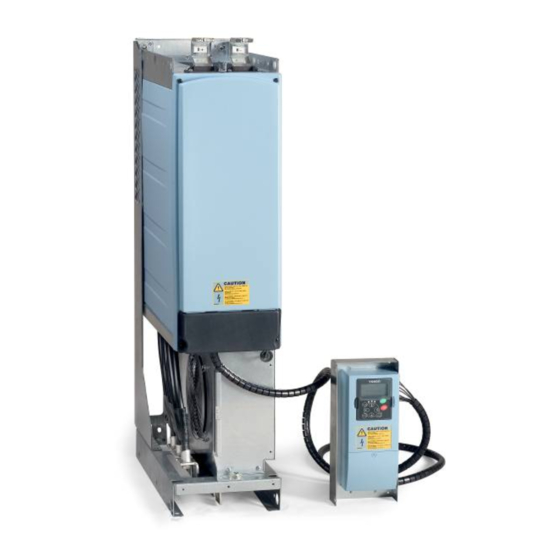
- Page 49 • 49 6.1.2.1 Vacon NXI frames Figure 6-9. Vacon NXI, FI9. Protection class IP00 Figure 6-10. Vacon NXI, FI10. Protection class IP00 24-hour support: +358-(0)40-8371 150 • Email: vacon@vacon.com...
- Page 50 50 • vacon cabling and connections Figure 6-11. Vacon NXI, F12. Protection class IP00 Figure 6-12. Vacon NXI, FI13. Protection class IP00 Tel: +358-201-2121 • Fax: +358-201-212 205...
- Page 51 Disconnect the motor cable from the motor and open the bridging connections in the motor connection box. Measure the insulation resistance of each motor winding. The measurement voltage must equal at least the motor nominal voltage but not exceed 1,000 V. The insulation resistance must be >1MΩ. 24-hour support: +358-(0)40-8371 150 • Email: vacon@vacon.com...
- Page 52 The I/O boards mounted at the factory are indicated in the type code. For more information on the option boards, see Vacon NX option board manual (ud741). The control board can be powered externally (+24V) by connecting the external power source to bidirectional terminal #6 (see Table 6-9).
- Page 53 The inverters are equipped with A1 and A2 boards as standard. The signal descriptions for the standard application are presented in Chapter 2 of the All in One Application Manual. You can find the signal descriptions for other applications in the Vacon NX Application Manual.
- Page 54 54 • vacon cabling and connections 6.2.1.1 Control cables The control cables shall be at least 0.5 mm screened multicore cables, see Table 6-9. The maximum terminal wire size is 2.5 mm for the relay terminals and 1.5 mm for other terminals.
- Page 55 Voltage 0—10V, R >1kΩ Selection with jumper block X3 (see page 58): Open collector output Maximum U = 48VDC Maximum current = 50 mA Table 6-10. Control I/O terminal signals on basic I/O board OPT-A1 24-hour support: +358-(0)40-8371 150 • Email: vacon@vacon.com...
- Page 56 56 • vacon cabling and connections OPT-A2 RO1/1 Relay output Switching capacity 24VDC/8A 250VAC/8A RO1/2 125VDC/0.4A RO1/3 Min.switching load 5V/10mA RO2/1 Relay output Switching capacity 24VDC/8A 250VAC/8A RO2/2 125VDC/0.4A RO2/3 Min.switching load 5V/10mA Table 6-11. Control I/O terminal signals on basic relay board OPT-A2...
- Page 57 On the A1 basic board, there are four jumper blocks (X1, X2, X3 and X6) each containing eight pins and two jumpers. The selection possibilities of the jumpers are shown on page 58 (Figure 6-21). Figure 6-20. Jumper blocks on OPT-A1 24-hour support: +358-(0)40-8371 150 • Email: vacon@vacon.com...
- Page 58 58 • vacon cabling and connections Jumper block X1: Jumper block X2: AI1 mode AI2 mode AI1 mode: 0...20mA; Current input AI2 mode : 0...20mA; Current input AI1 mode: Voltage input; 0...10V AI2 mode: Voltage input; 0...10V AI1 mode: Voltage input; 0...10V (differential) AI2 mode: Voltage input;...
-
Page 59: Control Keypad
• 59 CONTROL KEYPAD The control keypad is the link between the Vacon inverter and the user. The Vacon NX control keypad features an alphanumeric display with seven indicators for the Run status (RUN, , READY, STOP, ALARM, FAULT) and three indicators for the control place (I/O term/ Keypad/BusComm). - Page 60 60 • vacon control keypad READY = Lights up when AC power is on. In case of a trip, the symbol will not light up. ALARM = Indicates that the drive is running outside a certain limit and a warning is given.
- Page 61 = Description line; Displays the description of the menu, value or fault. ••• = Value line; Displays the numerical and textual values of references, parameters, etc. and the number of submenus available in each menu. 24-hour support: +358-(0)40-8371 150 • Email: vacon@vacon.com...
- Page 62 62 • vacon control keypad Keypad push-buttons The Vacon alphanumeric control keypad has 9 push-buttons that are used for controlling the inverter (and motor), setting parameters, and monitoring values. Figure 7-1 Keypad push-buttons 7.2.1 Button descriptions reset This button is used to reset active faults (see Chapter 7.3.3.4).
- Page 63 From there you will be able to navigate your way up to the desired menu using the menu and browser buttons. You will find more detailed descriptions of the menus later in this chapter. 24-hour support: +358-(0)40-8371 150 • Email: vacon@vacon.com...
- Page 64 64 • vacon control keypad READY R EADY R EADY I/Oterm I/Ote rm I/Oterm Expander boards A:NXOPTA1 Parameters G1 G5 G1 G1 P1 P3 STOP R EADY STOP R EADY Change I/Ote rm I/Ote rm enter value System Menu Language...
- Page 65 Digital and relay output statuses V1.15 Analogue output V1.16 Multimonitoring Displays three selectable monitoring values. See M1.17 items chapter 7.3.6.5. Table 7-1. Monitored signals Note! All in One applications may embody more monitoring values. 24-hour support: +358-(0)40-8371 150 • Email: vacon@vacon.com...
- Page 66 66 • vacon control keypad 7.3.2 Parameter menu (M2) Parameters are the way of conveying the commands of the user to the inverter. Parameter values Parameter Menu Main Menu can be edited by entering the from the when the location indication M2 is visible on the first line of the display.
- Page 67 Keypad Keypad Keypad Parameters Basic parameters Min Frequency P1 P18 G1 G8 13.95 Hz READY READY Keypad Keypad Min Frequency Min Frequency 13.95 Hz enter 14.45 Hz Figure 7-1. Parameter value change procedure 24-hour support: +358-(0)40-8371 150 • Email: vacon@vacon.com...
- Page 68 68 • vacon control keypad 7.3.3 Keypad control menu (M3) In the Keypad Control Menu , you can choose the control place, edit the frequency reference and Menu button right change the direction of the motor. You can enter the submenu level by pressing...
- Page 69 You can disable this function by giving parameter 3.4 the value 0. If the value of this parameter is 0, the STOP button will stop the motor only when the keypad has been selected as the active control place. 24-hour support: +358-(0)40-8371 150 • Email: vacon@vacon.com...
- Page 70 70 • vacon control keypad 7.3.4 Active faults menu (M4) You can enter the Active faults menu from the Main menu by pressing Menu button right when the location indication M4 is visible on the first line of the keypad display.
- Page 71 If the drive is unable to restart the motor after an AR fault an FT fault occurs. The 'FT fault' has basically the (Fault Trip) same effect as the F fault: the drive is stopped. Table 7-1. Fault types 24-hour support: +358-(0)40-8371 150 • Email: vacon@vacon.com...
- Page 72 Check the supply voltage. If it is voltage adequate, an internal failure has inverter internal fault occurred. Contact the nearest Vacon distributor. Please visit: http://www.vacon.com/wwcontacts.html Output phase Current measurement has detected that Check motor cable and motor.
- Page 73 (same type) Drive of same power rating or same type Note: No fault time data record! of board added. Device removed Option board removed. Reset Drive removed. Note: No fault time data record! 24-hour support: +358-(0)40-8371 150 • Email: vacon@vacon.com...
- Page 74 74 • vacon control keypad Device unknown Unknown option board or drive. Contact the nearest Vacon distributor. Please visit: http://www.vacon.com/wwcontacts.html IGBT temperature IGBT Inverter Bridge overtemperature Check loading. protection has detected too high a short Check motor size. term overload current...
- Page 75 * Tells the user if the drive was at zero speed (< 0.01 Hz) when the fault occurred Real time record If real time is set to run on the inverter, the data items T1 and T2 will appear as follows: Counted operation days yyyy-mm-dd Counted operation hours hh:mm:ss, 24-hour support: +358-(0)40-8371 150 • Email: vacon@vacon.com...
- Page 76 76 • vacon control keypad 7.3.5 Fault history menu (M5) Vikahistoriavalikkoon pääsee Päävalikosta painamalla Oikeanpuoleista valikkonäppäintä kun You Fault history menu Main menu Menu button right can enter the from the by pressing when the location indication M5 is visible on the first line of the keypad display.
- Page 77 System menu. The number of submenus and subpages is shown with the symbol S (or P) on the value line. Page 78 has a table of the functions available in the System menu. 24-hour support: +358-(0)40-8371 150 • Email: vacon@vacon.com...
- Page 78 78 • vacon control keypad System menu functions Code Function Unit Default Cust Selections English Deutsch Selection of S6.1 English Suomi language Svenska Italiano Basic Application Standard Application Local/Remote control Appl. Basic S6.2 Application selection Multi-Step Application Application PID Control Application Multi-Purpose Control Appl.
- Page 79 Application ID D6.8.4.#.2 Applications: version Applications: D6.8.4.#.3 firmware interface S6.8.5 Hardware I6.8.5.1 Unit power I6.8.5.2 Unit voltage I6.8.5.3 Info: Brake chopper I6.8.5.4 Info: Brake resistor S6.8.6 Expander boards Table 7-4. System menu functions 24-hour support: +358-(0)40-8371 150 • Email: vacon@vacon.com...
- Page 80 80 • vacon control keypad 7.3.6.1 Selection of language The Vacon control keypad offers you the possibility to control the inverter through the keypad in the language of your choice. System menu Locate the language selection page under the . Its location indication is S6.1. Press Menu button right once to enter the edit mode.
- Page 81 The drive resets automatically. Alternatively, you can choose any other storing or loading functions with the Browser buttons enter Confirm with the button. Wait until 'OK' appears on the display. 24-hour support: +358-(0)40-8371 150 • Email: vacon@vacon.com...
- Page 82 82 • vacon control keypad READY READY enter CONFIRM Parameter sets Parameter sets Select LoadFactDef CANCEL READY READY Parameter sets Parameter sets Wait... Figure 7-7. Storing and loading of parameter sets Upload parameters to keypad (To keypad, S6.3.2) This function uploads all existing parameter groups to the keypad provided that the drive is stopped.
- Page 83 Select with the When the Parameter backup function is activated Vacon NX control keypad makes a copy of the parameters of the presently used application. When applications are changed, you will be asked if you wish the parameters of the new application to be uploaded to the keypad. If you want to do this,...
- Page 84 84 • vacon control keypad READY READY Set1 ParamComparison C1 C3 READY READY Set1 P2.1.2= 50.0 P1 P6 20.0 Hz READY EDIT VALUE P2.1.2= 50.0 20.0 Hz CONFIRM CHANGE enter Figure 7-9. Parameter comparison 7.3.6.5 Safety Security submenu NOTE: The is protected with a password.
- Page 85 If you want to deactivate the function, follow the same procedure and give the parameter value READY READY READY I/O term I/Oterm I/Oterm enter CONFIRM Startup wizard Startup wizard Startup wizard CANCEL Figure 7-12. Activation of Start-up wizard 24-hour support: +358-(0)40-8371 150 • Email: vacon@vacon.com...
- Page 86 86 • vacon control keypad Multimonitoring items (P6.5.4) Vacon alphanumeric keypad features a display where you can monitor up to three actual values at Monitoring values the same time (see Chapter 7.3.1 and Chapter in the manual of the application you are using).
- Page 87 , you can determine how long the backlight stays on before going out. You can select any time between 1 and 65535 minutes or 'Forever'. For the value setting procedure, see Timeout time (P6.6.3). 24-hour support: +358-(0)40-8371 150 • Email: vacon@vacon.com...
- Page 88 88 • vacon control keypad 7.3.6.7 Hardware settings The Hardware settings submenu NOTE: is protected with a password. Store the password in a safe place! In the Hardware settings submenu (S6.7) under the System menu, you can further control some Internal brake functions of the hardware in your inverter.
- Page 89 . The current value starts to blink. Use the Browser buttons enter to change the acknowledgement time. Confirm the change with the button or return to the previous level with Menu button left. 24-hour support: +358-(0)40-8371 150 • Email: vacon@vacon.com...
- Page 90 90 • vacon control keypad READY READY I/Oterm I/Oterm HMI ACK timeout HMI ACK timeout enter 200ms 200ms Figure 7-19. HMI acknowledge timeout Number of retries to receive HMI acknowledgement (P6.7.4) With this parameter you can set the number of times the drive will try to receive acknowledgement if it does not receive acknowledgement within the acknowledgement time (P6.7.3) or if the received...
- Page 91 The following information is available: Page Content Name of application 6.8.4.# 6.8.4.#.1 Application ID 6.8.4.#.2 Version 6.8.4.#.3 Firmware interface Table 7-8. Applications information pages 24-hour support: +358-(0)40-8371 150 • Email: vacon@vacon.com...
- Page 92 92 • vacon control keypad In the Applications information page, press Menu button right to enter the Application pages of which there are as many as there are applications loaded into the inverter. Locate the desired Browser buttons Menu button right...
- Page 93 • 93 I/Oterm I/Oterm Software version B:NXOPTA2 E1 E2 10001.0 READY READY READY I/Oterm I/Oterm I/Oterm Expander boards A:NXOPTA1 State E1 E5 E1 E2 Figure 7-22. Expander board information menus 24-hour support: +358-(0)40-8371 150 • Email: vacon@vacon.com...
- Page 94 94 • vacon control keypad 7.3.7 Expander board menu (M7) Expander board menu In the the user can 1) see the expander boards connected to the control board and 2) see and edit the parameters associated with the expander boards.
- Page 95 • 95 Further keypad functions The Vacon NX control keypad contains additional application-related functions. See Vacon NX Application Package for more information. 24-hour support: +358-(0)40-8371 150 • Email: vacon@vacon.com...
-
Page 96: Commissioning
The motor terminals U, V, W and the DC-, DC+ terminals are live when Vacon NX inverter is connected to DC supply, even if the motor is not running. The control I/O-terminals are isolated from the mains potential. - Page 97 • 97 Set the parameters of group 1 according to the requirements of your application (See Vacon All in One Application Manual). At least the following parameters should be set: motor nominal voltage motor nominal frequency motor nominal speed motor nominal current You will find the values needed for the parameters on the motor rating plate.
- Page 98 98 • vacon commissioning Run the start-up tests without the motor being connected to the process. If this is not possible, make sure that running each test is safe prior to running it. Inform your co- workers of the tests.
-
Page 99: Fault Tracing
Check the supply voltage. If it is voltage adequate, an internal failure has inverter internal fault occurred. Contact the nearest Vacon distributor. Please visit: http://www.vacon.com/wwcontacts.html Input line Input line phase is missing. Check supply voltage and cable. supervision 24-hour support: +358-(0)40-8371 150 • Email: vacon@vacon.com... - Page 100 Brake chopper no brake resistor installed Check brake resistor. supervision brake resistor is broken If the resistor is ok, the chopper is brake chopper failure faulty. Contact the nearest Vacon distributor. Please visit: http://www.vacon.com/wwcontacts.html Inverter Heatsink temperature is under –10°C undertemperature...
- Page 101 Contact the nearest Vacon distributor. Please visit: http://www.vacon.com/wwcontacts.html PT100 board Temperature limit values set for the Find the cause of temperature rise temp. fault PT100 board parameters have been exceeded Table 9-1. Fault codes 24-hour support: +358-(0)40-8371 150 • Email: vacon@vacon.com...
- Page 102 Vaasa Helsinki Vacon Traction Oy Vacon Plc (Head office and production) Vacon Plc Vehnämyllynkatu 18 Runsorintie 7 Äyritie 12 33700 Tampere 65380 Vaasa 01510 Vantaa telephone: +358 (0)201 2121 firstname.lastname@vacon.com telephone: +358 (0)201 212 600 fax: +358 (0)201 212 710...
Need help?
Do you have a question about the FI9 and is the answer not in the manual?
Questions and answers