Advertisement
Quick Links
• READ ALL INSTRUCTIONS BEFORE ASSEMBLY AND USE OF GATE.
!
• KEEP INSTRUCTIONS FOR FUTURE USE.
www.carlsonpetproducts.com
Carlson Pet Products, Inc.
3200 Corporate Center Drive, Suite 105 | Burnsville, MN 55306, USA
952.435.1084
Made in China
OWNER'S MANUAL MODEL:
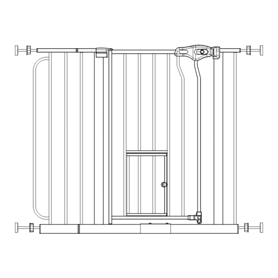
WALK-THROUGH ASSEMBLY GATE
0930 PW DS, 0941 PW DS
WITH SMALL PET DOOR
Advertisement

Related Manuals for Carlson 0930 PW DS


Summary of Contents for Carlson 0930 PW DS
- Page 1 0930 PW DS, 0941 PW DS OWNER’S MANUAL MODEL: WALK-THROUGH ASSEMBLY GATE WITH SMALL PET DOOR • READ ALL INSTRUCTIONS BEFORE ASSEMBLY AND USE OF GATE. • KEEP INSTRUCTIONS FOR FUTURE USE. www.carlsonpetproducts.com Carlson Pet Products, Inc. 3200 Corporate Center Drive, Suite 105 | Burnsville, MN 55306, USA 952.435.1084...
-
Page 2: Before Using Product
Before Using Product Read and follow all instructions carefully to ensure that your gate and extensions are properly installed. Improper installation could result in the gate becoming unstable or dislodged from the doorway. Please keep these instructions for your reference. WARNING •... -
Page 3: Before Assembly
Before Assembly PLEASE CHECK TO MAKE SURE YOU HAVE THE FOLLOWING PARTS: Wall Cups (4) Left Side Frame Half (1) 1" Wall Mount Screws (4) Gate Door Panel (1) Spring Loaded Upper Door Mounting Pin (1) Right Side Frame Half (1) Frame Assembly Screws (2) 6"... - Page 4 Extensions List NOTE 4" 6" 8" 12" MODEL MAX SIZE 0930 PW DS 29 – 38 inches 4" 6" 8" 12" MODEL MAX SIZE 0941 PW DS 29 – 38 inches WARNING: The gap between the gate and wall should not exceed more than 2.5 inches.
- Page 5 Assembling Your Gate STEP 1 Take the left and right gate frame halves and align the holes in the lower horizontal tube. Place the frame halves together and then using the frame assembly screws and hex key, tighten the two halves together. STEP 2 Lower the gate door into the assembled gate frame and insert the lower gate door pin into the mounting hole on the frame.
- Page 6 STEP 3 Align the hole in the upper corner of the gate door with the hole in the door mounting bracket. Insert the spring loaded mounting pin into the hole in the mounting bracket and the door. NOTE: Once the spring loaded mounting pin is inserted into the gate door hole, it cannot be taken out again by hand.
- Page 7 Installing Your Gate STEP 1 Locate the (4) threaded spindle rods. Rotate the adjustment wheels along the threading, eliminating the gap between the adjustment wheel and the rubber foot. ADJUSTMENT WHEEL RUBBER FOOT STEP 2 Insert the (4) threaded spindle rods into the holes at each of the four corners of the gate.
- Page 8 STEP 3 Position the gate so that it is level and centered within your doorway or opening. Rotate the adjustment wheels on the threaded spindle rods in the opposite direction as in STEP 1, expanding the gap between the rubber foot and the adjustment wheel. Expand each of the (4) threaded spindle rods until they make contact with the doorway or opening.
- Page 9 STEP 4 When you are satisfied with the general placement of your gate, fully tighten the threaded spindle rods attached to the lower corners of the gate by further rotating the adjustment wheels. Continue by tightening the upper threaded spindle rods. As you tighten the threaded spindle rods, you will notice the gap between the door frame and the easy slide latch begin to narrow.
- Page 10 Positioning and Attaching the Wall Cups Using the wall cups will affix your gate more firmly in the doorway or opening. This is the recommended way to use the gate. STEP 1 After you have mounted your gate, and you are satisfied with its positioning, draw a circle on the surface of your doorway or opening around the perimeter of the (4) rubber feet.
- Page 11 STEP 3 With the gate fully removed, you can now use the circles you marked during STEP 1 as guides for screwing in your (4) wall cups. Center each of the wall cups within the guide circles and use the provided self-tapping screws to fasten them in place via the hole through the center of each wall cup.
-
Page 12: Operating The Door
Operating the Door STEP 1 At the bottom of the gate door, rotate the base lock to the horizontal position. To allow the door to swing open in both directions, rotate the base lock on both sides. BASE LOCK STEP 2 Squeeze one or both of the circular buttons on the easy slide latch while simultaneously pulling back on one or both of the locking slides. - Page 13 Adding a Gate Extension STEP 1 Choose the side of the gate to be extended and remove the top and bottom threaded spindle rods. STEP 2 Assemble the gate and extension as illustrated. Reposition the gate and fit in accordance with the gate fitting instructions.
- Page 14 Carlson Pet Products, Inc. will replace or repair it at Carlson’s option. PROOF OF PURCHASE REQUIRED.
-
Page 15: Replacement Parts
Replacement Parts Threaded Spindle Rods Wall Cups Gray = #14015 w/Adjustment Wheel Gray = #14016 Top Plug Insert Pet Door Pull Lock Gray = #14020 White = #13038 Spring Loaded Upper Door Bottom Plug Insert Gray = #14019 Mounting Pin #10051 Easy Slide Latch w/All Frame Assembly Screws... - Page 16 Carlson Pet Products, Inc. 3200 Corporate Center Drive, Suite 105 Burnsville, MN 55306, USA 952.435.1084 20180221MS...
Need help?
Do you have a question about the 0930 PW DS and is the answer not in the manual?
Questions and answers